LiDAR applications become expensive detours when a team begins with a sensor demo instead of the decision the depth data must support. A compact module can show a convincing depth image and still leave the UAV, robot, inspection station, or AR/VR prototype without a defined mounting zone, representative target set, host-data contract, or acceptance record.
Start with one operational decision: detect a forward object, establish a low-altitude reference, hold or review a fixture zone, or test a near-field depth interaction. Then choose the first proof artifact for that decision. This guide gives an engineering team a practical route map for evaluating a compact dToF candidate without treating its data sheet as a finished system.
| Quick answer | For each application, define one decision, one physical zone, representative targets, the data handoff, and a written stop condition before judging sensor fit. |
|---|---|
| Best starting point | Use a compact dToF module as a candidate for a bounded evaluation—not as proof that a vehicle, robot, inspection station, or headset workflow is complete. |
| First deliverable | A one-page application proof sheet that names the decision, mount, distance envelope, target variations, host owner, and evidence to retain. |
LiDAR applications start with the decision, not a device category
“We need LiDAR” is not yet a testable requirement. Replace it with a sentence that a team can observe: “Before the next move, show whether this marked zone is clear,” or “At this height, provide the host with a usable ground-reference input.” The sentence tells the mechanical, controls, and procurement teams what must be visible, what happens next, and which evidence matters.
A 2025 NIST publication on 3D-lidar evaluation describes a common acquisition platform and static evaluation procedures in an automotive context. Its results are not a specification for another sensor or use case. The useful lesson here is narrower: make conditions, data collection, and the intended decision explicit before comparing outcomes.
For a general sequence of mounting, data capture, and evidence retention, see this compact dToF evaluation workflow. The matrix below adds the application-specific question that should shape the first pilot.
Four compact depth-sensing routes and their first proof artifacts
| Application route | Decision to define | First proof artifact | Do not conclude yet |
|---|---|---|---|
| UAV obstacle avoidance or altitude hold | Which sector or ground-reference zone must the host receive? | Mount-and-sector sketch plus a time-stamped target-pass log. | That a depth stream alone proves flight safety, braking, or controller behaviour. |
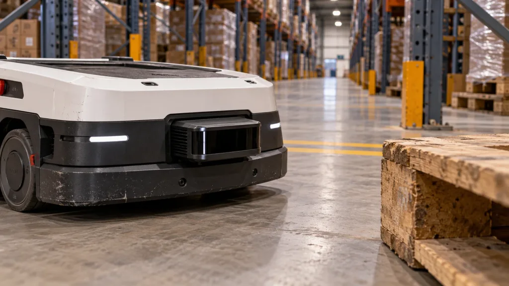
| Robot navigation and obstacle avoidance | Which aisle, approach, or keep-out zone changes the robot’s next action? | Coverage sketch, representative obstacle board, and unknown-data handling record. | That a point cloud alone proves navigation performance in every layout. |
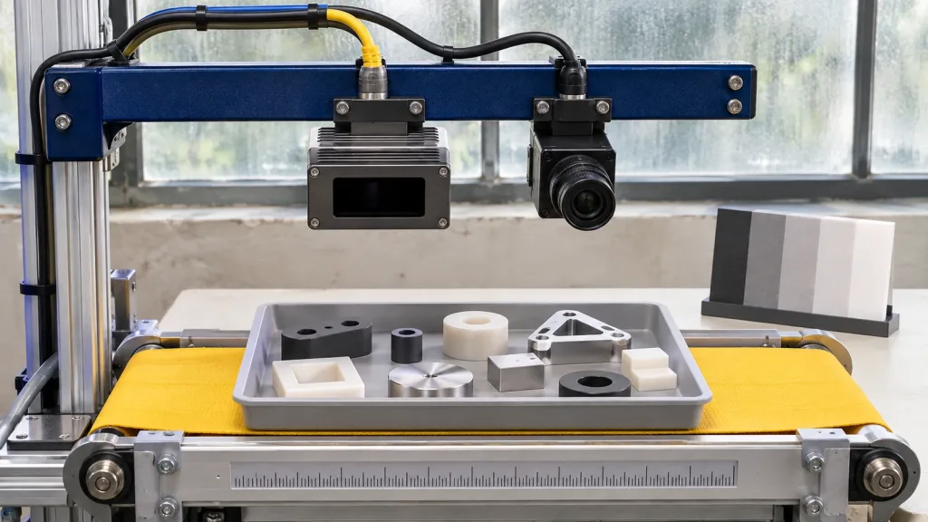
| Industrial inspection or security | Which physical condition results in pass, hold, or human review? | Fixture-zone drawing, good/bad sample set, and retained review images or records. | That a demonstration is a production acceptance result. |
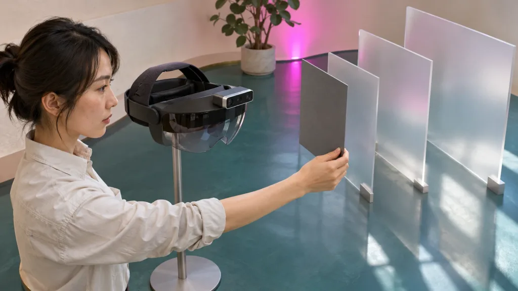
| AR/VR auxiliary focusing | Which near-field depth event must the prototype distinguish? | Interaction-zone sketch, representative surfaces, and a host-side event log. | That a module alone guarantees a finished user interaction or optical design. |
Route 1: UAV depth evidence has a separate controller handoff
For an aircraft pilot, write down whether the initial proof concerns a forward obstacle sector, a side sector, or a downward ground-reference zone. Measure the proposed mount position against propellers, airframe obstructions, expected pitch/roll attitudes, and the target distances that matter to the test. Retain the sensor output and the host’s interpreted state as separate records.
That separation matters because a complete aircraft function includes the host processor, perception logic, planning, flight controller, operating mode, and a validated response. Purpleriver’s sensor-to-flight-controller data contract is a useful companion for defining the handoff. As one implementation example, official ArduPilot object-avoidance documentation shows that available avoidance behaviour varies by vehicle and mode. Confirm the documentation and test method for the actual host; do not infer compatibility or a safety function from a module demonstration.
Route 2: robot navigation needs a usable-zone proof
A navigation pilot is not a request for “more points.” It is a request to preserve enough geometry for the robot’s next decision. Mark the must-see floor-to-object zone, the smallest relevant obstacle, likely occlusions from chassis or payload, and how the host represents unavailable versus clear data. Then run target passes at the distances, headings, materials, and motion patterns that the pilot will actually encounter.
Keep this first proof bounded. A result in one aisle, around one dock, or with one object set is evidence for that defined pilot—not a claim about every facility. If the next phase needs a stream check before navigation tuning, use the depth-stream validation tutorial to structure that handoff.
Route 3: inspection starts with the station decision
In an inspection or security pilot, the best first question is usually not “Can the module see the part?” It is “Which observable depth condition changes the station from pass to hold to review?” Draw that zone, specify the allowable occlusions, and collect representative parts, finishes, orientations, and empty-station conditions. A good pilot preserves enough evidence for a reviewer to understand why a given cycle was classified.
For a more focused station-planning example, see the 3D depth sensor workcell validation guide. Keep the promised outcome modest: the pilot should establish whether the proposed zone and evidence record are useful, not claim a finished inspection system.
Route 4: AR/VR calls for an interaction-zone test
For auxiliary focusing or a near-field depth prototype, define the portion of the interaction space that matters and what the host must do when depth is unavailable, unstable, or outside the intended zone. Test the surfaces, angles, and user-adjacent objects that are plausible for the prototype. A depth module may supply data to a host-side experiment; it does not by itself settle optical design, application logic, or the user experience.
The AR/VR near-field prototype guide can help translate that zone into a bounded experiment and a reviewable record.
Published MRP-LD1 baseline: use it to screen a pilot, not to skip one
The Featured-product export identifies the MRP-LD1 Drone LiDAR Sensor as a compact solid-state SPAD dToF candidate for evaluation. Its published values can help a team decide what to test first; they do not replace testing the intended target, mount, motion, environment, or host behaviour.
| Published field | MRP-LD1 baseline | Evaluation implication |
|---|---|---|
| Architecture | Solid-state SPAD dToF with 940 nm VCSEL | Confirm the intended application can use the supplied depth and point-cloud data. |
| Weight, power, supply | 8 g; 1.2 W; 5 V | Check the actual mounting, power budget, grounding, and thermal arrangement of the prototype. |
| Coverage and capture | 60° × 45° FOV; 40 × 30 resolution; 10 fps | Draw the must-see zone rather than assuming all application geometry falls inside it. |
| Published range baseline | 0.5–25 m indoors; 0.2–8 m outdoors; 80 Klux ambient-light resistance | Test the intended target, angle, ambient light, mounting, and motion before setting an operating boundary. |
| Output and host paths | Depth and point-cloud output; UART, UVC, UDP; Windows, ARM, Linux, Android support | Select one host path and document framing, data ownership, timing, errors, and recovery for the pilot. |
| Published application groups | Robot navigation/obstacle avoidance; UAV obstacle avoidance/altitude hold; AR/VR auxiliary focusing; industrial inspection/security | Choose one bounded decision from the relevant group before requesting a conclusion about fit. |
Review the current MRP-LD1 product baseline with the project team. The listing states that actual usable range depends on target, ambient light, angle, mounting, and motion; it also states that the host-side system remains part of a complete obstacle-avoidance solution.
Build one representative target board before comparing application results
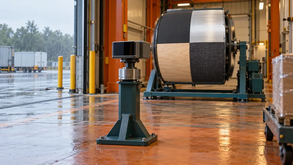
Every route benefits from a target board or target set that resembles the real decision: the relevant matte and reflective surfaces, useful angles, expected distances, and at least one difficult or ambiguous condition. Mark which target is present in each recording. This turns a persuasive demonstration into evidence that another engineer can review.
Why be this deliberate? A primary flash-lidar study of material properties found that return waveforms in its experimental system were affected by distance, incidence angle, and reflecting material; colour and angle also complicated the paper’s material-classification task. Those findings are not MRP-LD1 performance claims. They are a sound reason to include the real target conditions in the evaluation rather than trusting a single flat, front-facing test card.
Define the data and integration handoff before tuning behaviour
Choose the host path—UART, UVC, or UDP—only after naming the consumer. Then document the depth or point-cloud payload the consumer needs, its expected frame or coordinate convention, timing ownership, invalid-data semantics, storage policy, and recovery path. The project should be able to answer: who sees a stale or missing sample, what state is emitted, and who decides whether to pause, review, or continue?
Do this before controller tuning or application logic. A capture tool can make a stream look healthy while the real consumer has a different timing, transform, buffering, or failure-handling requirement. A written data contract makes that gap visible early.
Illustrative application case: a loading-bay pilot that does not overclaim
Imagine a facilities team considering a compact depth sensor for a covered loading-bay transfer zone. Its first decision is modest: before a pallet cart enters a marked area, determine whether the zone should continue, hold for review, or be treated as unavailable. The team is not yet claiming autonomous navigation or a production safety function.
- It marks the decision zone and sketches the proposed sensor mount, including brackets and cart positions that may obscure it.
- It assembles a target set that includes the cart, an empty zone, common packaging surfaces, and intentionally awkward viewing angles.
- It records depth/point-cloud output, the host’s classification, and the reason for every hold or unavailable result.
- It reviews missed, ambiguous, and false-positive cases before changing the zone, mount, or host rule.
This is a realistic way to learn whether the proposed application decision and data handoff are well formed. It does not transfer results to a UAV, a robot in another building, or a different surface set.
Common mistakes when scoping a LiDAR application
- Starting with a market label. “Warehouse,” “drone,” or “AR” is too broad; name the next decision and physical zone.
- Using one friendly target. Include representative materials, angles, and empty/ambiguous cases in the first proof.
- Confusing data availability with application behaviour. Keep the sensor record, host interpretation, and controller or station response separately testable.
- Assuming an interface answers the integration question. UART, UVC, and UDP describe paths, not the consumer’s data contract or failure policy.
- Calling a small pilot a completed system. Retain scope boundaries and review conditions; expand only after the first decision is evidenced.
RFQ and pilot checklist: what to send before asking for a sample or quote
| Send this | Why it matters |
|---|---|
| Named application decision and diagram of the must-see zone | Lets the evaluation focus on what the host needs to decide. |
| Working distance, indoor/outdoor setting, mounting idea, and expected motion | Lets the team compare the scene against published baselines without turning them into promises. |
| Representative target materials, shapes, finishes, and angles | Creates a test set that resembles the intended use. |
| Host system and preferred UART, UVC, or UDP path | Starts the data contract and integration review. |
| Required records, review owner, and project timing | Sets an evidence trail and makes the sample conversation actionable. |
Turn a LiDAR application into a reviewable pilot
Share the platform, one decision zone, working distance, scene, host system, preferred interface, representative targets, sample quantity, and project timing. Purpleriver can then provide the relevant product documents, SDK resources, sample data, evaluation-sample discussion, or project-specific quote path for the MRP-LD1 candidate.