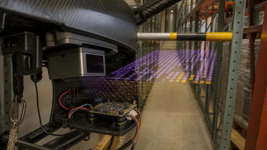
A LiDAR sensor can display plausible ranges on a bench and still be unsafe to hand to a flight controller. The failure often sits between the optical measurement and the control loop: an old frame looks current, a body-frame direction is mistaken for north, an unknown sector becomes “clear,” or invalid pixels are silently converted to zero. By the time a pilot build exposes the mistake, the team is debugging three systems at once.
This guide defines a nine-field data contract for the sensor-to-host boundary. It gives UAV integration engineers a practical way to capture evidence, replay edge cases, inject faults, and decide whether a range or point-cloud stream is ready for controlled controller testing.
Quick answer: what must a LiDAR sensor data contract contain?
A usable contract states the acquisition time and clock, coordinate frame and orientation, field of view, measurement bounds and units, invalid-value rules, confidence semantics, payload layout, freshness and delay budget, and fault behavior. Each field needs a pass/fail test and a retained artifact such as a raw capture, decoded frame, transform check, timeout trace, or controller log. A transport label—UART, UVC, or UDP—does not define these semantics by itself.
Why a data contract comes before controller integration
A flight controller does not act on “a point cloud” in the abstract. It acts on values that have been timestamped, transformed, filtered, classified as valid or invalid, and delivered within a known age. Every unrecorded assumption at that boundary becomes a possible control defect.
Start by separating three layers:
- Measurement layer: what the sensor reports, including range limits, field of view, resolution, confidence or invalid samples.
- Transport layer: how bytes or frames cross UART, UVC, or UDP, including ordering, size, framing, loss detection, and restart behavior.
- Control layer: how the host maps measurements into a vehicle frame, checks freshness, fuses coverage, and constrains velocity or position.
This separation prevents a successful cable test from being mistaken for a successful control integration. If the project has not chosen a transport yet, first review the practical differences in UART, UVC, and UDP LiDAR interfaces. Then document the same semantic contract regardless of which transport carries it.
LiDAR sensor acceptance table: nine fields and their proof
The table is deliberately evidence-oriented. “Documented” is not the same as “observed.” A field passes only when the team can show that its decoder, transforms, timeouts, and logs preserve the documented meaning.
| Contract field | Questions to resolve | Minimum pass evidence | Failure consequence |
|---|---|---|---|
| 1. Acquisition time | What event does the timestamp represent? Which clock and epoch are used? Can clocks drift or jump? | Raw sensor/host captures with a stated clock domain, monotonicity test, and measured frame age | Old obstacles look current; fusion aligns measurements from different moments |
| 2. Frame and orientation | Where is the origin? Which axes and handedness apply? Is the orientation fixed or supplied per frame? | A physical left/right/up/down target test plus a recorded transform into the vehicle body frame | A forward obstacle can be mapped to the wrong sector |
| 3. FOV and coverage | Are horizontal and vertical FOVs full angles? How do pixels or bins map to rays? Which sectors are unobserved? | Angular target sweep with observed edge bins and an explicit “no coverage” mask | Unseen space is treated as clear space |
| 4. Bounds and units | What are the minimum and maximum reportable ranges? Are units metres, centimetres, or raw codes? | Near-bound, in-range, and beyond-bound captures with unit conversion tests | A scale error or clipped value changes clearance by orders of magnitude |
| 5. Invalid and unknown values | How are too-near, too-far, no-return, saturated, unknown, and unused samples distinguished? | A decoder truth table and synthetic packets for every invalid state | Zero, maximum range, and unknown collapse into a dangerous single meaning |
| 6. Quality and variance | Is quality per pixel or per frame? What does zero mean? Are thresholds fixed or application-specific? | Contrasting-target and lighting captures that retain quality/validity fields beside distance | Weak or ambiguous returns enter the controller as equally trusted ranges |
| 7. Payload layout | What are dimensions, field types, byte order, stride, sequence, and optional fields? | A byte-level fixture with known decoded values and checks for length, stride, and endianness | A decoder can produce plausible but spatially scrambled data |
| 8. Freshness and delay | What update rate is sustained? What are acquisition, transport, processing, and control delays? | Latency percentiles and age-at-consumption from host/controller logs, including load and loss cases | The stopping calculation uses a nominal frame rate instead of actual data age |
| 9. Fault behavior | What happens after dropped frames, corruption, disconnect, clock reset, or sensor restart? | Fault-injection traces showing detection, bounded recovery, diagnostic state, and conservative output | The last good frame persists indefinitely or recovery silently changes semantics |
Use exact MRP-LD1 facts as test inputs—not as integration proof
The Featured MRP-LD1 Drone LiDAR Sensor provides concrete limits for building a worksheet. These listed parameters define what to test. They do not prove end-to-end latency, controller compatibility, packet mapping, or performance on a particular airframe.
| Featured-product field | Listed value | How it enters the data-contract test |
|---|---|---|
| Ranging / scanning principle | dToF / SPAD | Keep validity and confidence beside every derived range |
| Wavelength | 940 nm VCSEL | Record test lighting and target condition with each capture |
| Listed range | 0.5–25 m indoors; 0.2–8 m outdoors | Test inside, at, and beyond the applicable bound; do not merge indoor and outdoor limits |
| Listed accuracy | 0.2–1 m ≤±3 cm; 1–5 m ≤±5 cm; 5–8 m ≤±10 cm; 8–15 m ≤±20 cm | Define separate acceptance bins rather than one all-range tolerance |
| Field of view | 60° horizontal × 45° vertical | Build an angular coverage map and preserve uncovered sectors |
| Resolution / frame rate | 40×30 / 10 fps | Check the 1,200-position organization and measure age; 10 fps is not an end-to-end latency result |
| Interfaces | UART, UVC, UDP | Choose a transport, then verify its documented framing and the common semantic contract |
| Host software listing | Windows, ARM, Linux, Android | Confirm the exact deliverable, version, and sample code needed for the selected host |
| Power / weight | 5 V; 1.2 W; 8 g | Measure the integrated rail and timing under the project’s harness and compute stack |
| Ambient-light resistance | 80 Klux | Include measured illumination and target reflectivity in the validation matrix |
| Temperature | Operating -20–60 °C; storage -30–70 °C | Keep environmental state with logs; do not infer a system-level qualification |
| Laser safety listing | Class 1 (FDA Recognized Eye-Safe) | Request the applicable product evidence and preserve the exact configuration identity |
Range data versus an organized point cloud: preserve meaning through the conversion
A nearest-range array and a 3D point cloud can originate from the same depth frame, but they are not interchangeable.
A range representation needs a direction or angular bin for each value, explicit minimum and maximum limits, and distinct states for obstacle, no obstacle, and unknown. A point-cloud representation additionally needs a coordinate frame, field definitions, dimensions, row and point stride, byte order, and invalid-point handling. If a 40×30 depth image becomes an organized cloud, the host should demonstrate that row/column order and XYZ placement survive conversion.
For early inspection, use the site’s guide to visualizing dToF depth data, but retain machine-readable captures as the acceptance artifact. A screenshot cannot reveal a swapped byte order, a stale timestamp, or an invalid pixel that was coerced to zero.
Make one “golden frame” fixture with deliberately varied depths across rows and columns. Decode it on every target platform. Assert dimensions, sample order, units, frame ID, and invalid locations. This small fixture catches more integration errors than repeatedly viewing a flat wall.
A four-stage workflow from raw capture to controller-bound evidence
Stage 1: capture without control
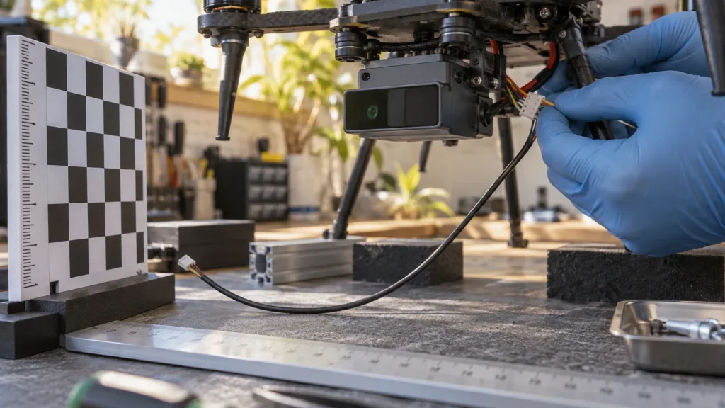
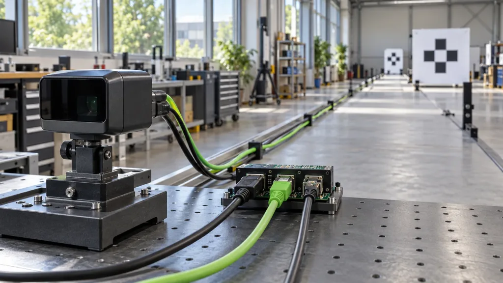
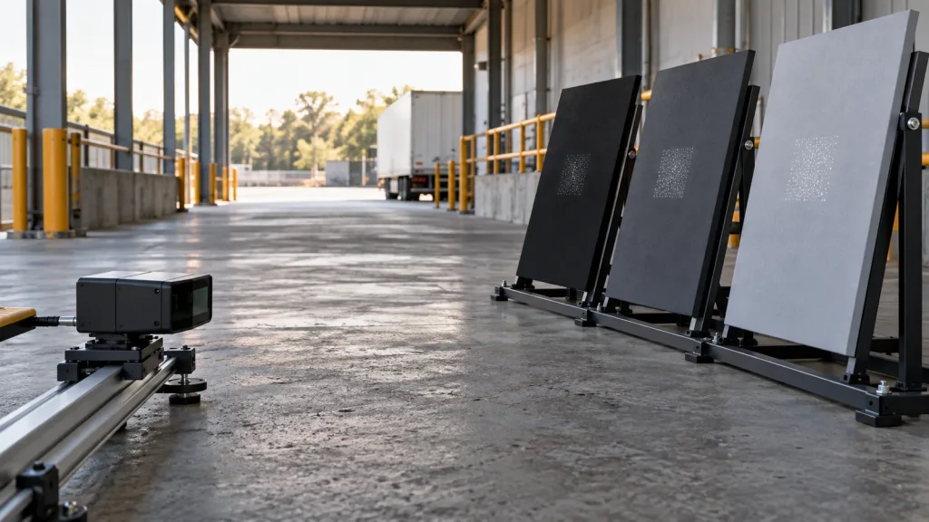
Place known targets at the centre and near each FOV boundary. Include a dark matte surface, a more reflective surface, an empty sector, and a target outside the listed range. Capture the unmodified transport data, host receive time, decoder output, illumination measurement, target description, sensor configuration identity, and software version.
Do not tune filters until the raw behavior is retained. The raw file is what allows the team to separate optical behavior from a parser or controller defect later.
Stage 2: semantic replay
Replay a fixed capture into the decoder without the sensor attached. Verify units, axis direction, pixel order, bounds, and invalid states with automated assertions. Rotate the expected sensor-to-body transform and confirm that left, right, up, and down move to the intended vehicle sectors.
The pass condition is deterministic: the same capture and configuration produce the same decoded frame, and every transform is traceable to a named coordinate convention.
Stage 3: freshness and fault injection
Delay frames, duplicate one sequence, drop a burst, corrupt a length or checksum where the documented transport permits detection, disconnect the stream, and restart the sensor. The host should expose data age and transition to a conservative state. It must not present the last good obstacle map as indefinitely fresh.
Use both the sensor acquisition time and the host/controller consumption time. Update rate answers “how often”; age answers “how old was the information when the decision used it.” Measure both under realistic compute and link load.
Stage 4: controller-bound test under containment
Only after the decoder passes should the team connect the output to a simulator, hardware-in-the-loop setup, restrained test rig, or other controlled environment appropriate to its safety process. Record the obstacle input, transformed sectors, velocity/setpoint response, delay configuration, and fault state on the same timeline.
Autopilot behavior is implementation-specific. For example, current PX4 collision-prevention documentation describes coverage sectors, a configurable delay budget, conservative handling of missing coverage, a warning after more than 0.5 seconds without range data, and a later transition to Hold. Treat those behaviors as requirements to verify for the chosen stack, not as universal defaults.
Example case: a rack-aisle crossbar exposes four silent contract errors
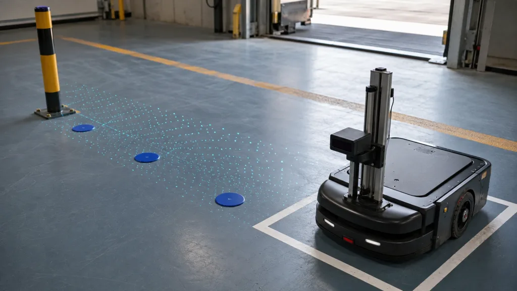
This is an evaluation scenario, not a customer result. An indoor UAV team mounts a compact dToF module facing forward and prepares a contained approach toward a horizontal crossbar in a warehouse rack aisle. The team uses the MRP-LD1’s listed 60°×45° FOV, 40×30 output, 10 fps frame rate, and indoor range as planning inputs.
- Frame test: a target moves from image-left to image-right. The transformed body-frame obstacle must move through the corresponding sectors, with no mirror or 90° rotation.
- Unknown test: several angular cells are marked unknown in replay. The host must preserve them as unknown rather than fill them with maximum range.
- Freshness test: the stream pauses while the last frame shows open space. The controller-facing layer must reject the stale frame according to the project’s timeout.
- Target test: the crossbar is presented with dark and more reflective coverings under recorded lighting. Distance, validity, and any available quality indicator are retained together.
The case passes only when the report ties each control response to an input timestamp, transform, validity map, and software/configuration identity. “The drone stopped in the demo” is an observation; the synchronized evidence explains whether it can be reproduced.
UART, UVC, and UDP: document the transport boundary without inventing a protocol
MRP-LD1 lists UART, UVC, and UDP, but a project still needs the product documentation or SDK that defines the selected mapping. Do not infer baud rate, packet length, pixel format, port, checksum, or ROS/MAVLink compatibility from the interface name alone.
- UART worksheet: electrical level, connector/pinout, framing, baud rate, direction, byte order, length, integrity check, frame sequence, timeout, and restart behavior.
- UVC worksheet: negotiated format and dimensions, payload interpretation, timestamp source, dropped-frame indication, host buffering, and device re-enumeration.
- UDP worksheet: addressing/ports, datagram-to-frame assembly, ordering, loss and duplicate handling, integrity, timestamps, socket buffering, and reconnect behavior.
For each, save a raw capture and a decoded fixture. Then use the site’s LiDAR integration diagnostic guide to keep power, wiring, transport, parser, and application failures in separate branches.
Common mistakes that make a LiDAR stream look more trustworthy than it is
- Using receive time as acquisition time without saying so. Queueing and buffering disappear from the log even though the data are older.
- Assuming maximum range means no obstacle. Maximum, out-of-range, no-return, invalid, and uncovered can require different actions.
- Rotating the visualization but not the data. A viewer can look correct while the controller consumes a different frame.
- Quoting 10 fps as 100 ms total latency. Frame period is only one component; acquisition phase, transport, decode, scheduling, fusion, and control tracking add delay.
- Dropping the validity or quality channel. A clean distance array may hide why a sample was uncertain or rejected.
- Testing only a flat, bright wall. That does not exercise edge coverage, contrast, unknown cells, mixed ranges, or target-dependent return behavior.
- Letting the last frame live forever. Every consumer needs an age limit and an observable stale state.
- Claiming controller or ROS support from a transport name. UART/UVC/UDP describe transports; the exact application mapping must be supplied and validated.
RFQ and evaluation checklist for the sensor-to-host contract
Attach this list to the sample request and assign an owner for every answer:
- Exact product/hardware revision and firmware identity
- Selected interface and its current protocol or data-format document
- Connector/pinout and electrical requirements for that interface
- Timestamp definition, clock domain, epoch, resolution, and reset behavior
- Coordinate-frame, axis, origin, orientation, and FOV-to-pixel/bin mapping
- Units, bounds, scaling, byte order, payload dimensions, and stride
- All invalid, unknown, too-near, too-far, saturation, and no-return codes
- Available quality, confidence, variance, status, or diagnostic fields
- Frame sequence, integrity check, loss/duplicate handling, timeout, and recovery behavior
- SDK/sample-code deliverables for the chosen Windows, ARM, Linux, or Android host
- Raw example captures that include valid and invalid measurements
- Configuration-change and document-revision history for pilot traceability
Purpleriver’s documentation resource page is the appropriate starting point for requesting the files available for an evaluation. Include the intended host, interface, application, range window, and evidence needed by the review team.
Turn the data contract into a sample-evaluation plan
Send Purpleriver the UAV platform, host operating system, preferred UART/UVC/UDP interface, required range window, and the packet, timing, and fault evidence your controller review needs. The team can confirm which MRP-LD1 documents and evaluation materials are available without assuming an undocumented protocol or compatibility claim.