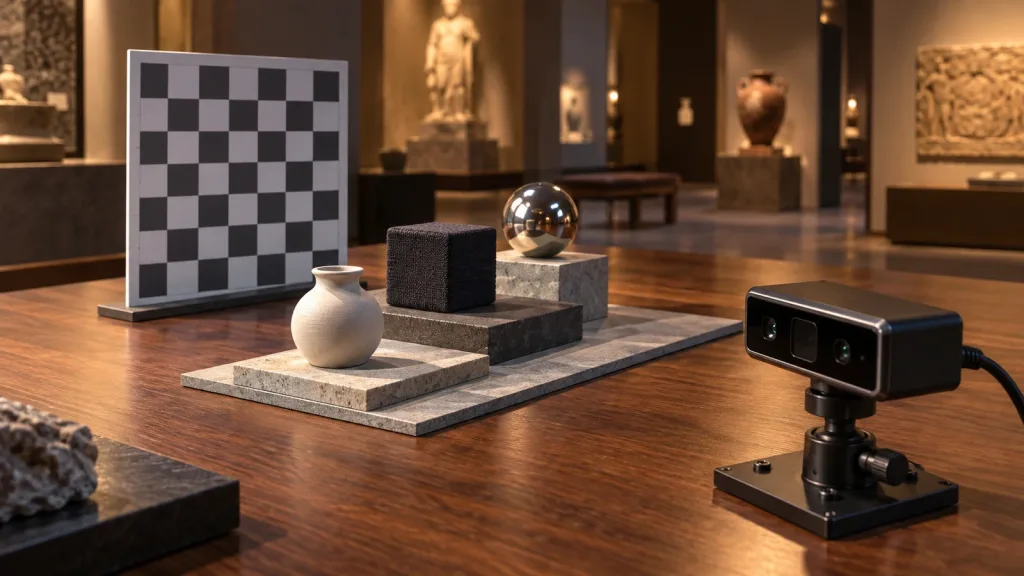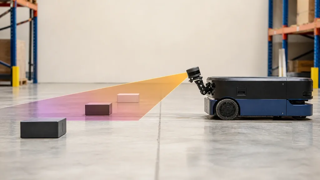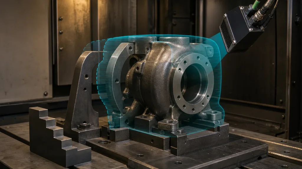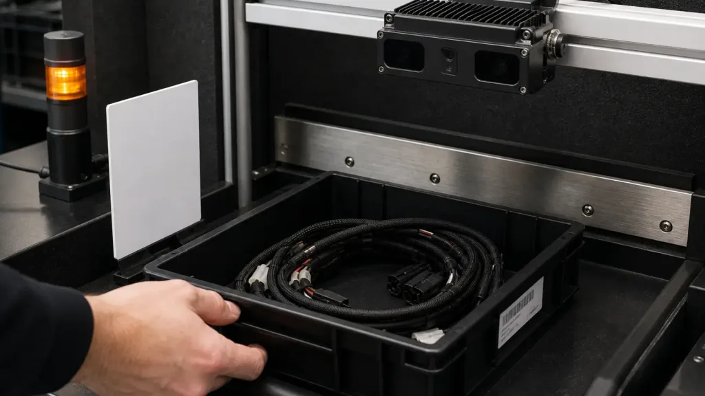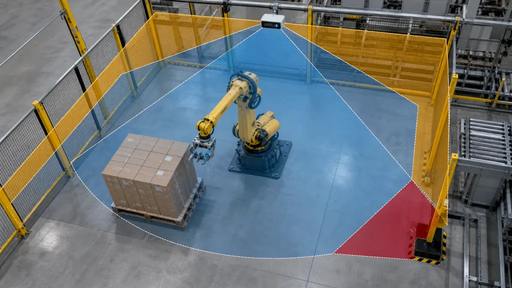
3D depth sensor projects for robot-cell zone monitoring usually fail for practical reasons, not because the sensor category is wrong. Teams miss blind spots around posts and pallets, define alarm zones too late, or discover after bench testing that the output handoff does not fit the PLC, robot controller, or logging workflow they planned to use.
This guide is written for automation engineers and technical buyers who need to validate a compact sensing module for industrial monitoring, pallet-edge checks, and robot-cell intrusion awareness before they approve a pilot cell or request more hardware.
| Quick answer | Use a compact 3D depth sensor only after you prove the mounting height, zone geometry, blind-spot coverage, and data handoff match the robot cell you actually need to monitor. |
|---|---|
| Best fit | Teams validating short-range industrial monitoring, pallet-edge detection, and zone-intrusion awareness around robot workcells. |
| Decision rule | If you cannot define what counts as a valid zone event, a nuisance stop, and a missed obstacle, the sensor is not ready for procurement approval. |
Why a 3D depth sensor is useful for robot-cell monitoring
A compact depth sensor is attractive when a team needs near-field spatial awareness in a constrained industrial cell, not just a single distance value. STMicroelectronics positions Time-of-Flight sensing for robotics and industrial use cases where compact integration and spatial measurement matter, and that is the right starting point for cell monitoring decisions. The engineering question is not whether the category sounds modern. It is whether the sensor can see the right zone edges, maintain stable coverage around real fixtures, and deliver usable data into the control path you already own.
That is why validation has to be geometry-first. NIST’s work on point-cloud evaluation is useful here because it pushes teams toward measurable comparisons instead of visual impressions alone. In a robot cell, that translates into hard questions:
- Can the sensor see pallet corners, fence openings, and approach lanes from the mounting position you can actually build?
- Can the workcell distinguish a real zone intrusion from a nuisance event caused by reflections, occlusion, or unstable thresholds?
- Can the output be handed off into the robot-side or PLC-side logic without adding a fragile custom bridge?
If you need background on the industrial side of compact dToF modules first, Purpleriver already has a related article on industrial inspection with compact dToF LiDAR modules. This article goes one step further by focusing on acceptance criteria for a monitored zone.
3D depth sensor decision table for industrial teams
| Evaluation area | What to verify | Why it matters in a robot cell | Reject if |
|---|---|---|---|
| Zone coverage | Mounting height, horizontal and vertical field of view, dead zones near posts and fences | A coverage gap at floor level or at pallet height is where real incidents are missed | The monitored zone does not fully cover the approach geometry you defined |
| Detection stability | Repeatability across target materials, lighting, and motion speed | Unstable depth events create nuisance stops and operator distrust | You cannot define a stable trigger threshold over repeated test cycles |
| Output usefulness | Depth grid, point cloud, intrusion region, or event signal | The output type determines how much system logic must be built downstream | The control stack needs a format the sensor cannot provide or you cannot process |
| Industrial fit | Power, interfaces, logging workflow, and environmental assumptions | A good lab sensor still fails if maintenance and integration are awkward on the line | Bench bring-up requires tools or custom middleware the cell team will not support |
| False-stop tolerance | How the cell behaves when reflections, occlusion, or partial targets appear | Availability drops if the system stops production too often | No practical nuisance-event filter can be defined |
Exact featured-product parameters to validate first
Purpleriver’s current WooCommerce Featured product for this workflow is the LiDAR Drone Module – MRP-LD1 Solid-State dToF Sensor. If you are screening it as a 3D depth sensor for industrial monitoring, these exported product fields are the baseline facts to test against your own zone geometry and system logic.
| Parameter | Published value | Evaluation implication |
|---|---|---|
| Weight | 8 g | Useful when a sensor must mount on a slim pole, enclosure bracket, or compact robot fixture. |
| Power / supply | 1.2 W at 5 V | Check cabinet power margins and cable-routing practicality early. |
| Ranging principle | dTOF with SPAD scanning | Expect spatial depth output and validate event logic using actual scene geometry. |
| Emitter | 940 nm VCSEL | Review enclosure window and optical-path assumptions before final mechanical design. |
| Laser safety | Class 1 | Useful for product screening, but still document the operating context and mounting plan. |
| Range | Indoor 0.5-25 m; outdoor 0.2-8 m | For robot cells, convert this into the specific monitored distances that matter at floor and pallet height. |
| Ambient light resistance | 80 Klux | Still test plant lighting and reflective materials instead of assuming the headline figure solves every scene. |
| Accuracy | 0.2-1 m <= +/-3 cm; 1-5 m <= +/-5 cm; 5-8 m <= +/-10 cm; 8-15 m <= +/-20 cm | Translate this into the minimum separation margin your zone logic requires. |
| FoV | 60° x 45° | Model whether one sensor covers the cell edge or whether obstructions create a blind wedge. |
| Resolution / rate | 40 x 30 at 10 fps | Check whether the cell needs richer spatial granularity or whether coarse zone logic is sufficient. |
| Interfaces | UART / UVC / UDP | Pick the path that best matches logging, replay, and controller handoff. |
| Software support | Windows / ARM / Linux / Android | Useful if the bench workflow and deployed edge system span different environments. |
A practical 3D depth sensor validation workflow before approval
1. Define the monitored zone in physical terms
Write down the zone you actually care about: pallet entry edge, operator approach corridor, robot-arm swing boundary, or handoff station. Then specify which object sizes must trigger a response, the minimum warning distance, and the type of event the controls team expects. A zone-monitoring project becomes vague very quickly when the team never turns “watch this area” into dimensions and acceptance thresholds.
2. Model blind spots before you mount hardware
A 60° x 45° field of view may be enough for a compact cell, but only if you account for the enclosure lip, fence posts, cable routing, and pallet stack height. Draw the zone in side and top view. Mark where the lower edge of the sensor coverage meets the floor and where the side boundaries miss corners. That is the easiest place to catch an avoidable design error.
3. Pick the simplest logging path first
The MRP-LD1 support for UART, UVC, and UDP is useful because you can separate early data collection from final controls integration. Start with the interface that makes depth capture and replay easiest, then move to the controller-side path later. Purpleriver’s documentation hub, sample datasets, and the existing guide on choosing the right LiDAR interface are the most relevant internal checkpoints at this stage.
4. Bench-test with acceptance metrics, not screenshots
The depth image only matters if it supports a repeatable decision. A compact workcell test sheet should capture:
- detection success at fixed pallet and fixture positions,
- blind-spot size near fences, posts, and corner geometry,
- nuisance events caused by reflective wrap, glossy cartons, or mixed-height targets,
- latency from sensor event to controller-side usable signal,
- repeatability across multiple approach directions.
The recent SPAD dToF ranging-precision paper is useful background because it shows that dToF performance is shaped by operating conditions and design choices, not just by a single headline number. For a buyer or integrator, the practical meaning is simple: run the validation in the geometry and material mix of the real cell.
5. Define the handoff path before you sign off on the sensor
Many projects stall after good bench data because the controls team never agreed on what the sensor should output to the rest of the system. Decide whether you need a raw depth grid, a filtered intrusion event, or a higher-level zone status. If the output path is unclear, the perception decision is premature. Purpleriver’s troubleshooting article on common LiDAR integration issues is useful here because most schedule slips happen at the interface between sensor behavior and system behavior.
Interface, data, and handoff checks
The technical handoff is where a promising demo becomes either a deployable subsystem or another engineering detour. Keep the discussion concrete.
| Integration topic | Questions to answer |
|---|---|
| Mounting | Can the sensor see the floor edge and pallet approach area without fence or bracket occlusion? |
| Data model | Will the downstream logic consume a depth grid, a filtered point cloud, or a zone event? |
| Controller handoff | What exact signal or message will the PLC, edge computer, or robot controller receive? |
| Replay workflow | Can missed events and nuisance events be replayed with synchronized cell context? |
| Maintenance | How will cleaning, window inspection, and threshold re-validation be handled in production? |
| Output interpretation | Who owns the conversion from raw depth output to an actionable zone state? |
If your team needs a refresher on how output style changes downstream work, Purpleriver’s article on depth map vs point cloud is still relevant even though it was written for a different audience. The decision is the same: use only the output complexity your application can support.
Realistic application case: palletizing cell with a side-entry approach zone
Consider a palletizing workcell where cartons arrive near the robot envelope and empty pallets are exchanged by operators or mobile handling equipment. The team does not need full-scene mapping. It needs dependable awareness of a side-entry zone, one pallet corner at floor height, and a fence opening where partial intrusions can occur.
A practical evaluation workflow is:
- Mount the sensor at the realistic post height, not at an idealized lab angle.
- Measure coverage at floor level, pallet height, and the expected approach line of the operator or pallet jack.
- Replay reflective and partial-target events to see where nuisance stops begin.
- Verify whether a one-sensor geometry leaves a blind wedge near a fence post or pallet stack.
- Confirm that the chosen output can be handed into the cell logic without a brittle custom parser.
This kind of use case fits the exported MRP-LD1 application scope for industrial inspection and zone-intrusion-style monitoring while staying inside the product facts actually available to this workflow.
Common mistakes when screening a 3D depth sensor
- Testing the sensor on open benches and never rebuilding the same geometry with posts, fencing, and pallets.
- Approving a field of view number without translating it into floor coverage and corner visibility.
- Assuming any depth output is useful before the controls team defines the required handoff format.
- Ignoring nuisance-stop behavior caused by reflective materials or partial targets.
- Choosing a richer output format than the actual PLC or edge workflow can maintain.
- Failing to define how cleaning, drift checks, and threshold re-validation will be handled after installation.
RFQ and engineering evaluation checklist
| Checklist item | Why it belongs in the RFQ or sample request |
|---|---|
| Exact zone geometry and monitored object sizes | Prevents a generic spec review from replacing a real coverage decision. |
| Mounting constraints and enclosure assumptions | Blind spots often come from mechanics, not sensing theory. |
| Preferred bench interface and replay workflow | Shortens time to first meaningful evaluation. |
| Target output type for controls integration | Keeps perception work aligned with PLC or robot-controller needs. |
| Expected nuisance-event tolerance | Defines what level of false stop is acceptable before production is affected. |
| Plant lighting and reflective-material conditions | Ensures the test plan matches the real environment. |
| Validation ownership across controls, robotics, and maintenance teams | Avoids late-stage blame shifting when output interpretation fails. |
When a compact 3D depth sensor is the right next step
If your team can already define the monitored zone, the object sizes that matter, and the handoff signal your control stack expects, a compact solid-state module can move from bench validation into a realistic cell pilot quickly. If those definitions are still vague, tighten the acceptance sheet before buying more hardware.
Purpleriver’s featured MRP-LD1 solid-state dToF sensor is relevant for teams evaluating robotics perception, industrial inspection, zone monitoring, and short-range depth sensing. To discuss fit with your own workcell geometry, use the contact page and include the monitored zone dimensions, mounting position, and required output path.