Integration & SDK
LiDAR Integration Tutorials: Validate a Depth Stream Before Navigation Tuning
Before an integration team tunes mapping, collision logic, or a flight controller, it needs one smaller result: proof that the host can identify, receive, interpret, and retain a repeatable LiDAR depth stream. This first-hour acceptance plan turns a powered sensor into evidence an engineer can hand to the next stage.
Quick answer
Start LiDAR integration by making a small host-side acceptance record—not by opening a navigation demo. Record the sensor and interface configuration, capture a known scene, state what each depth or point-cloud field means, label the capture time and physical frame, deliberately observe invalid or missing data, and save a compact evidence bundle. Only then is application tuning based on data you can trace.
Why a depth-stream check comes before navigation
A LiDAR demo can look convincing while hiding the questions that later stall an integration: Which physical device produced this sample? What interface setting was active? Are the values depth, a point cloud, or an undecoded payload? Which direction does the sensor face? What does the host do when a sample is late or unusable?
Those questions are not paperwork. A planner, visualizer, or controller can only make a defensible decision when the data has an identity, a meaning, and a known relationship to the platform. The practical benefit is simple: isolate sensor-to-host uncertainty before it becomes a vehicle or robot behavior problem.
| If the team can answer this | Then proceed to | If it cannot |
|---|---|---|
| Which sensor, firmware/document set, host, interface, and configuration produced the capture? | Capture a controlled reference scene. | Freeze application work and record the setup identity first. |
| Can the host show a live stream and retain a short raw sample? | Declare the payload contract. | Diagnose power, cabling, host selection, and interface configuration. |
| Are dimensions, units, invalid values, ordering, time, and sensor frame documented? | Connect a visualizer or application adapter. | Do not treat anonymous bytes as navigation input. |
| Has the team observed a gap, timeout, or invalid-data condition and recorded its response? | Design the application’s safe behavior. | Keep the integration at the acceptance-test stage. |
For a companion reference on selecting the physical path, see UART, UVC or UDP: Choosing the Right LiDAR Interface. The choice is important, but interface selection alone does not prove that a host understands the resulting data.
LiDAR integration tutorials: the six-step depth-stream acceptance workflow
1. Create a one-page identity record
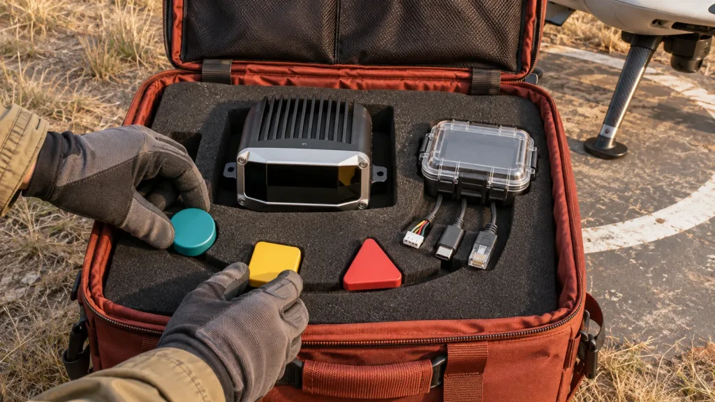
Write down the product name, sample identifier if available, host platform, power arrangement, physical mounting orientation, chosen interface, cable or network path, and the exact documentation or software version used. Attach a photograph of the installation and a timestamped terminal or application log. This lets another engineer reproduce the starting point without guessing.
2. Make one controlled scene observable
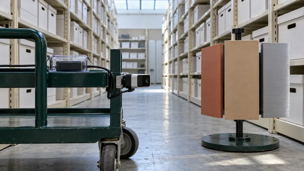
Use a simple, safe scene that has more than one visible depth relationship: for example, a near matte panel, a farther wall, and a clear edge between them. Do not use the result to claim range or accuracy. The immediate goal is more modest: verify that changing the scene produces an understandable change in the host’s displayed or logged data. For a useful next inspection step, see Visualizing dToF Depth Data for Early Product Testing.
3. Declare the payload contract before converting it
Keep a short statement beside the raw capture: the source interface; packet, frame, or image boundaries; dimensions; byte order where applicable; field names; units; invalid or confidence conventions; and the expected cadence. A contract may be incomplete on day one, but every unknown should be marked as unknown rather than silently guessed.
When a team adapts the data into a ROS-compatible cloud, the official PointCloud2 message definition is a helpful example of why dimensions, field layout, point step, row step, and data should be explicit. It is a data-model reference, not evidence that any particular sensor publishes ROS messages.
4. Label time and coordinate frames
Record when the host received or captured each sample, and write down the relationship between the sensor’s optical/depth frame and the platform body frame. If a team uses ROS conventions, ROS REP 105 provides a useful model for naming and documenting frame relationships. The key is not adopting a particular framework; it is making a later transform or timestamp interpretation reviewable.
For UAV integrations, this is the handoff that keeps a depth direction from being confused with the airframe’s forward, down, or body direction. For mobile robots, it keeps a sensor observation from being treated as a map-frame location without a documented transform.
5. Test an invalid or missing-data condition deliberately
Define a benign test that does not endanger equipment or people: temporarily stop the receiving process, disconnect only during a powered-down test stage, or present a scene that the team expects to flag for inspection. Record what the host reports, how it timestamps the event, what the application would do, and how normal streaming resumes. A zero value, an empty cloud, or a stale timestamp is not automatically a safe clearance decision; it is a condition that needs an explicit interpretation.
This matters especially where a host uses UDP. The IETF definition of UDP does not guarantee ordered, reliable delivery or duplicate protection. That is why a host-side test should observe its own timeout, gap, and sequencing behavior instead of assuming a datagram stream behaves like an ordered file.
6. Retain a small evidence bundle
Save the identity record, one short raw capture, a rendered screenshot or image of the controlled scene, the payload contract, a frame/time note, and the result of the invalid-data check. This bundle is much more useful to the next engineer than a verbal “the sensor works.” It also gives a clean basis for a supplier support question or a later acceptance test.
MRP-LD1 facts to use in an evaluation plan
Purpleriver’s Featured-product export identifies the MRP-LD1 Drone LiDAR Sensor as an evaluation module that supplies real-time depth images and 3D point-cloud data. The table below repeats only exported product facts; it does not turn them into a promise for an untested installation.
| Output | Real-time depth images and 3D point-cloud data |
|---|---|
| Documented interfaces | UART, UVC, UDP |
| Resolution / frame rate | 40 × 30; 10 fps |
| Field of view | 60° horizontal × 45° vertical |
| Evaluation range baseline | 0.5–25 m indoors; 0.2–8 m outdoors |
| Ambient-light baseline | 80 Klux |
| Power / mass | 5 V; 1.2 W; 8 g |
| Software support listed | Windows, ARM, Linux, Android |
Actual usable range and behavior depend on target, ambient light, angle, mounting, motion, and the intended scene, so use the published values to design a test—not to skip one. The product source does not state a ROS driver, a generic packet schema, or application-level obstacle-avoidance behavior; an integration plan should not assume any of them.
Interfaces, data, and the host-side questions that prevent rework
The MRP-LD1 documents UART, UVC, and UDP. Pick the path your host and evaluation objective can observe clearly, then ask the same core questions for every path:
- UART: What serial parameters, framing, and decoder document are in use? Can the host save bytes around a parser error?
- UVC: What format and mode has the host selected? What image dimensions and interpretation are expected for this evaluation?
- UDP: Which address, port, capture boundary, and timeout behavior are the host actually using? How will the application distinguish a fresh sample from a stale one?
Do not make a transport comparison article do the job of a data acceptance test. After the first bundle exists, the team can use Integrating a dToF LiDAR Module With Raspberry Pi and Linux for a host-side reference, or review Depth Map vs Point Cloud before choosing the representation needed by the next application stage.
Application case: a small AMR prototype in a test corridor
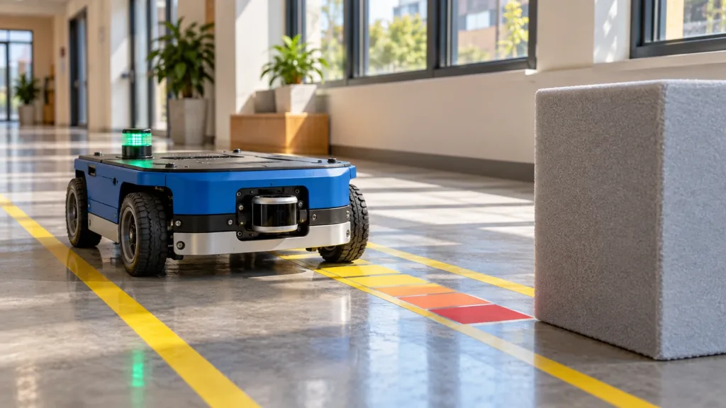
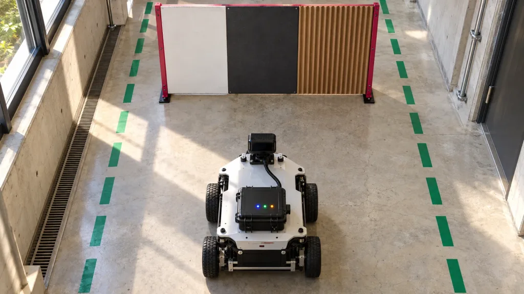
Imagine a team mounting a compact depth module at the front of a wheeled indoor prototype. It wants to use depth information in a later corridor-navigation trial, but it has not yet connected any planner. The team first points the platform toward three stationary materials at different distances, records the host configuration, saves a short data capture, and notes the sensor-to-body mounting direction.
Next, the team renders the stream, checks that the stored fields match its documented interpretation, and writes down what it will call invalid or stale data. The test’s pass condition is not “the robot avoided an obstacle.” It is “the team can replay, identify, and explain this capture.” That is a realistic handoff from a sensor evaluation to a separate navigation task, with no invented performance result.
Common LiDAR integration mistakes
- Starting with autonomy. A navigation stack can hide an undecoded, flipped, stale, or mislabeled stream.
- Calling a sample “a point cloud” without declaring its fields. Preserve the raw source and document the interpretation.
- Confusing an interface with an application protocol. UART, UVC, and UDP describe paths; they do not by themselves define an application’s data semantics.
- Leaving mounting direction in someone’s memory. Put the sensor-to-body orientation in the acceptance record.
- Treating invalid data as a distance measurement. Make an explicit invalid/stale-data rule before a planner consumes the stream.
- Reporting “it works” without an artifact. Save the short capture and the configuration that created it.
If a capture remains unexplained, move to a focused diagnostic path rather than changing several variables at once: Common LiDAR Integration Issues and How to Diagnose Them.
RFQ or evaluation request checklist
When asking for an evaluation sample, documents, or support, include enough context for the response to address the integration rather than a generic product inquiry:
- Target platform and application: UAV, robot, AR/VR, inspection, or another evaluation case.
- Working distance and whether the intended scene is indoor or outdoor.
- Host operating environment and preferred interface: UART, UVC, or UDP.
- The output you plan to inspect first: depth images, point-cloud data, or both.
- Mounting orientation, target materials, motion, and ambient-light conditions to be tested.
- Whether you need product documents, SDK resources, sample data, an evaluation sample, or a project-specific quote.
- Sample quantity and expected project timing.
Make the first integration test answerable
Use the MRP-LD1 product page to request product documents, SDK resources, sample data, an evaluation sample, or a project-specific quote. Bring the acceptance checklist above so the discussion begins with your host, scene, interface, and evidence needs—not assumptions.