Application-fit guide for perception engineers
Machine Vision 3D Camera: Build a Depth-and-Vision Evidence Plan
A machine vision 3D camera decision is rarely a choice between “depth” and “vision.” For a compact robot, inspection fixture, or UAV prototype, the useful question is narrower: which job should an active depth input do, which job still needs image understanding, and what evidence will prove that handoff in the intended scene?
This guide gives an evaluation plan for a compact dToF module as one depth-and-point-cloud input. It does not promise object recognition, obstacle avoidance, navigation, surveying, or system safety. Those outcomes depend on the complete optics, host, software, integration, operating envelope, and validation process.
Quick answer
Use a compact dToF module when your prototype needs registered distance observations in a defined near-field scene and you can validate them against real targets, light, motion, and data handling. Keep RGB/stereo or other perception tools when the task also requires semantic recognition, fine texture, broad scene interpretation, or a different depth envelope. Start by defining the depth job, then test the complete data path before assigning the sensor a control or safety role.
1. Assign the depth role before choosing the stack
“3D camera” covers different ways of producing spatial data. Optical time-of-flight systems estimate distance from emitted light and a returned signal; a NIST reference on optical ToF range cameras explains the measurement principle. Stereo systems, in contrast, infer geometry from corresponding image features. Neither label alone tells an engineer whether the resulting data are sufficient for a particular inspection or motion decision.
Give the depth input one explicit first job. Examples include placing a parcel within a known working zone, confirming clearance at a fixture entrance, measuring an approach-distance trend, or adding a near-field depth layer beside an image-based detector. A team can then state what counts as useful: target presence, point continuity, depth stability, latency, recovery after a dropped stream, or a specific point-cloud quality measure.
This discipline prevents a common category error: treating a depth frame as automatic semantic understanding. A sensor can report distance without identifying material, part number, defect class, safe route, or an approved response. If recognition is required, document how the image or model component supplies it and how the two streams are synchronized and calibrated.
2. Use the decision chart to define the first pilot
| Project question | Useful first evidence | What not to assume |
|---|---|---|
| Do we need a depth/proximity layer in a constrained zone? | Repeat captures of representative targets at the required distances, angles, and lighting states. | That a depth image alone identifies the target or guarantees a response. |
| Do we need shape, texture, or classification? | Labelled image-data evaluation with the intended recognition model and failure cases. | That a compact depth grid replaces RGB or stereo imagery. |
| Do we need a point cloud for a host-side prototype? | Documented coordinate frame, units, invalid-value handling, timestamps, and retained captures. | That “point-cloud output” establishes a finished middleware driver or application. |
| Will the scene include sunlight, dark materials, shiny parts, edges, or motion? | A matrix that varies one condition at a time and preserves raw samples. | That a stated ambient-light baseline covers every target, angle, window, and motion case. |
| Will data inform an actuator or vehicle? | End-to-end age, loss, restart, host behavior, and project-defined response tests on the complete system. | That sensor frame rate or range alone proves system performance or safety. |
A peer-reviewed ToF-camera metrology study identifies effects including illumination, reflectivity, temperature, depth distortion, and temporal variation, and concludes that application-specific evaluation matters. Use that as a reason to build an evidence plan, not as a prediction of MRP-LD1 results.
3. Screen the documented MRP-LD1 facts
The MRP-LD1 Drone LiDAR Sensor is a compact solid-state SPAD dToF module for evaluation. The table is a transcription of the supplied Featured-product information. It is a screening baseline: validate the final mount, target set, host, and scene before relying on any value in a project decision.
| Documented item | Supplied value | Evaluation question |
|---|---|---|
| Architecture | Solid-state SPAD dToF; 940 nm VCSEL | Does the proposed optical path, mounting window, and scene fit the depth test plan? |
| Indoor / outdoor stated range | 0.5–25 m indoors; 0.2–8 m outdoors | Which representative distances sit within the intended evaluation envelope? |
| Ambient-light baseline | 80 klux | How will the installed system be tested with the target reflectance, sun direction, and window condition? |
| Field of view and resolution | 60° horizontal × 45° vertical; 40 × 30 | How many meaningful depth samples cover the smallest required feature at each test distance? |
| Frame rate | 10 fps | What is the complete acquisition-to-host age and jitter under the planned workload? |
| Output and interfaces | Depth images and 3D point-cloud data; UART, UVC, UDP | Which interface and parser will preserve timestamps, data validity, and recovery behavior? |
| Integration facts | 5 V supply; 8 g; 1.2 W; Windows/ARM/Linux/Android software support | What power, mechanical, host, and software evidence is still needed for this build? |
The product information supports a module evaluation. It does not establish a native ROS package, full object-recognition pipeline, complete collision-avoidance system, or certified safety function. For a foundation before integration, see the site’s compact dToF evaluation workflow.
4. Build a depth-and-vision evidence plan
Start with a modest, repeatable test cell rather than an open-ended demo. Write the question on the test sheet: for example, “Can the host retain usable depth observations of the designated fixture edge in the required working zone while the image pipeline assigns the part class?” This phrasing keeps geometric measurement and semantic recognition separately testable.
- Freeze the physical reference. Record the sensor optical center, viewing direction, bracket revision, target coordinates, mounting window, power path, and cable routing.
- Make the target set representative. Include the actual size, materials, finishes, angles, backgrounds, and distance bands the project needs. Do not infer performance from a single white flat target.
- Capture raw and interpreted records. For every run, retain the source depth frame or cloud, the host receipt time, validity/confidence handling, and any resulting image-model output. A cleaned visualization alone cannot reveal whether a failure occurred in sensing, transport, transformation, or inference.
- Sweep conditions deliberately. Change one factor at a time: distance, yaw, pitch, target reflectance, ambient condition, scene background, motion, and the sensor-window state. Repeat after warm-up and after restarting the input path.
- Set project-specific pass rules. The responsible engineering team should define its own tolerances, persistence rule, permitted data age, recovery time, and required action. This article does not provide universal values.
- Review failures by layer. Classify each miss as illumination/target, geometry, raw-depth validity, interface/transport, time alignment, calibration/transform, application logic, or a combination. Then preserve the sample that led to the conclusion.
For background on why compact ToF cameras are often evaluated alongside other sensing methods rather than as a universal replacement, consult this peer-reviewed ToF–stereo fusion study. Its results do not transfer performance values to a particular module or application; it supports evaluating complementary inputs and the complete workflow.
5. Define the data handoff before software tuning
Many early evaluations fail because a visually plausible point cloud is handed to a host without a data contract. Document whether each timestamp marks acquisition, reception, or application publication; name the sensor frame and transform; state depth units, point ordering, invalid values, confidence treatment, and loss/restart detection. If an image and depth stream will be fused, retain the calibration version and the method used to align them.
Choose an interface from the actual prototype constraints. The MRP-LD1 lists UART, UVC, and UDP. That creates interface options, not a guarantee that every host parser, camera framework, or network path has been implemented for the project. The UART, UVC, or UDP selection guide can help structure the tradeoff; the team must still confirm the current protocol documentation, host behavior, and throughput on its hardware.
Decide whether the immediate application consumes a depth map or a point cloud. A depth map may make a near-field image-alignment or zone test straightforward; a cloud may fit a spatial filter or geometry review. The site’s depth-map versus point-cloud guide and point-cloud dataset evaluation checklist provide useful handoff questions.
6. Illustrative case: a packaging cell needs depth plus part context
Illustrative engineering scenario, not a customer result: a team is piloting a packaging-cell toolhead that approaches trays of mixed components. It needs two distinct answers: is there an object in the defined pre-pick zone, and which component family is visible?
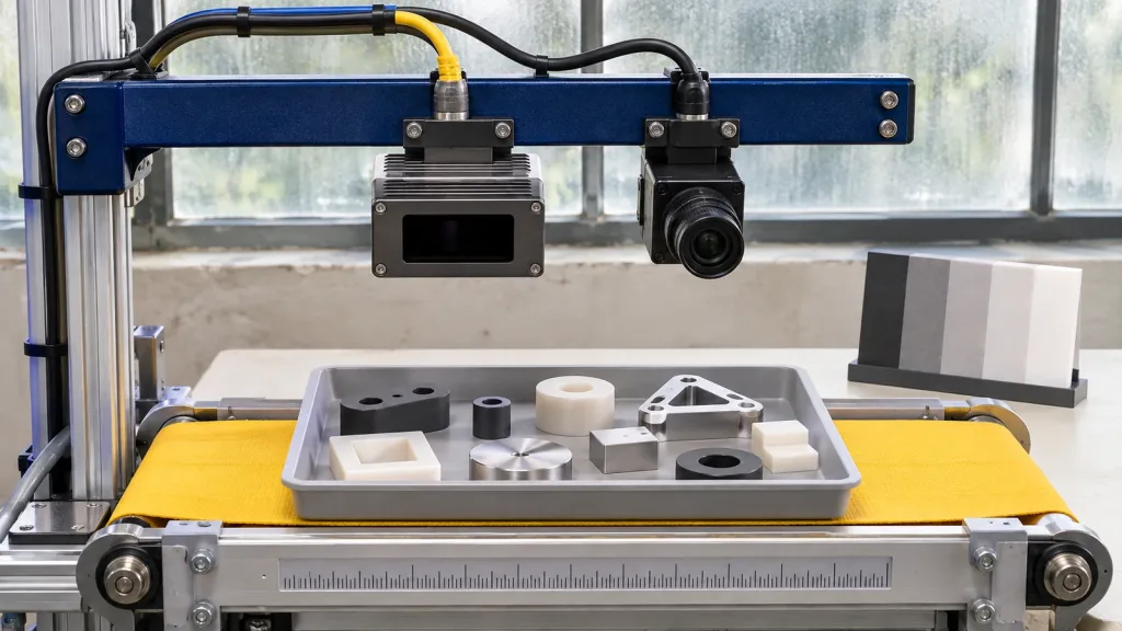
The team mounts a compact dToF module so that its documented field of view covers the pre-pick zone and retains an RGB camera for part-context experiments. It creates a tray matrix with a matte polymer part, a darker part, a metal-like surface, empty pockets, changing backgrounds, and several approach positions. Each capture records the raw depth sample, RGB frame, time relationship, transform version, target label, and host result.
The first review finds a depth discontinuity at some pocket edges. Rather than tuning a threshold until the dashboard looks clean, the team compares the raw samples, target position, illumination, and calibration record. It adjusts the test plan, then decides whether the depth input can support the pre-pick condition under its declared envelope. The recognition model remains a separate qualification item. This produces a useful pilot record without claiming that either sensor alone solves the cell.
7. Common machine-vision depth mistakes
- Calling any range sensor a complete vision stack. Distance, segmentation, classification, planning, and actuation are separate responsibilities.
- Testing only a bright, perpendicular target. The intended target set must include relevant reflectance, angle, edge, background, and motion conditions.
- Using the stated outdoor range or 80 klux baseline as a blanket application guarantee. Validate the installed geometry and scene.
- Comparing pretty displays instead of raw evidence. Save frames or clouds, timestamps, parameters, and the application decision for every trial.
- Forgetting time alignment. An apparently correct depth-image overlay can be wrong if streams describe different moments.
- Hiding invalid values too early. Invalid data are diagnostic evidence; document how the host detects and handles them.
- Assuming listed platform support proves a complete driver path. Verify the interface, protocol, SDK scope, parser, and version actually used.
- Turning a prototype threshold into a safety claim. Keep the system’s risk process, safeguards, and approved operating behavior separate from a sensor trial.
8. RFQ and evaluation-sample checklist
Send a defined measurement question with an RFQ or evaluation request. It will produce a more useful conversation than simply asking whether a sensor “works for machine vision.” Include:
- the application task, object types, smallest relevant feature, distances, approach directions, and required decision;
- indoor/outdoor conditions, expected light sources, target materials, colors, finishes, window condition, motion, vibration, and contamination questions;
- the proposed mechanical frame, FOV coverage sketch, host platform, power arrangement, and preferred UART, UVC, or UDP path;
- needed output form, coordinate convention, timestamp meaning, units, invalid-value/confidence representation, sample captures, and documentation;
- the image/stereo/other sensor that will supply semantic context, plus calibration and synchronization expectations;
- pass/fail evidence, retained logs, acceptance owner, version/change controls, and the boundary between prototype behavior and the final system’s safety process; and
- the sample quantity and project timing needed for a controlled evaluation.
Use the site’s industrial inspection overview for another application framing, and request the current documentation resources before committing engineering work.
Turn your application question into an evaluation plan
Share the target type, required working distances, lighting conditions, host platform, intended data path, and whether depth will be paired with an image stream. Purpleriver can help compare those inputs with the MRP-LD1’s published parameters and identify questions for an evaluation sample.