Quick answer: Validate drone obstacle avoidance in sunlight with a matrix, not a single “sunny day” flight. Vary measured ambient illumination, target finish/reflectivity, incidence angle, distance, target size, and motion. Record valid-pixel rate, distance bias and scatter, dropout-burst length, latency, and the controller response to invalid data. A klux specification is one boundary condition—not proof that every obstacle will be detected outdoors.
Why drone obstacle avoidance in sunlight depends on the target
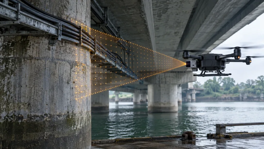
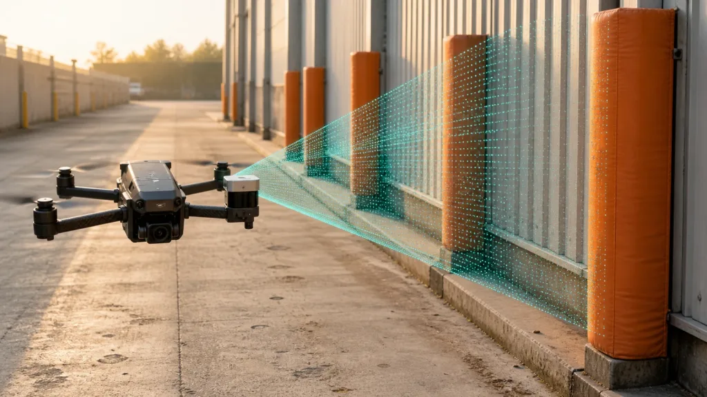
Direct time-of-flight LiDAR emits short optical pulses and estimates distance from return timing. Outdoors, the receiver also sees background photons. A dark or oblique surface may return fewer useful photons toward the receiver, while a bright background increases noise. Range, target size, beam footprint, optical window, incidence angle, surface finish, atmospheric effects, exposure/aggregation, and processing all influence the observed depth result.
A peer-reviewed Scientific Reports model of SPAD flash-LiDAR depth imaging explicitly includes target reflectivity, scattering, receiver optics, pixels, and photon statistics. Research on background-light rejection in SPAD LiDAR explains that outdoor background photons can cause false or degraded measurements and that rejection methods trade against other performance factors. These sources support a test philosophy: illumination and target return must be evaluated together.
Do not label targets only by color. Two black materials can have different near-infrared returns, and gloss can redirect the return away from the receiver at one angle but create a strong highlight at another. If reflectance matters to acceptance, use characterized reference materials or measure the samples at the relevant wavelength with suitable equipment. Otherwise describe them operationally—material, finish, angle, size, and condition—and preserve the actual test pieces.
Build a sunlight and reflectivity matrix
| Factor | Suggested levels | Why it matters |
|---|---|---|
| Ambient illumination | Indoor baseline; open shade; oblique sun; strong direct-sun condition measured at the target | Changes background photon load and can vary quickly with clouds and orientation |
| Target finish | Matte dark; matte mid-tone; matte light; glossy; retroreflective/metal only if mission-relevant | Changes useful return strength and multipath/specular behavior |
| Incidence angle | Near-normal plus several oblique angles up to the mission boundary | Return toward the receiver can fall as the surface turns away |
| Distance | Near boundary, braking threshold, nominal range, and outer test bound | Signal return and footprint change with distance |
| Target size/edge | Large plane, narrow pole, partial target, sector edge | A few valid pixels may be filtered or diluted in spatial reduction |
| Motion | Static, closing, crossing, yaw/pitch transition | Tests temporal filtering, frame-to-frame loss, and controller freshness |
| Surface condition | Dry baseline; dusty or wet only if approved operations require it | Contamination and specular water can change returns |
Use a fractional design only after a screening run shows which interactions are unimportant. For safety-critical cells, repeat across different times or controlled sources because ambient conditions drift. Record illuminance at the target plane and sensor orientation to the sun, plus weather, cloud, temperature, optical-window state, target ID, distance, and angle.
Illuminance in lux is weighted for human vision; it is still useful for reproducing a supplier’s klux boundary, but it does not completely describe spectral irradiance at 940 nm. Treat lux as a controlled observable, not a complete optical model.
Measure depth quality and decision quality separately
| Metric | Definition to freeze before testing | Decision use |
|---|---|---|
| Valid-pixel rate | Valid depth pixels inside the known target mask / expected target pixels | Shows whether the target is represented strongly enough for host logic |
| Detection probability | Trials where the target produces an approved obstacle decision / total trials | Connects sensor output to the obstacle pipeline |
| Bias | Mean or median reported range minus reference distance | Reveals systematic shift by light, finish, or angle |
| Scatter | Chosen dispersion statistic across accepted samples | Supports uncertainty margin and filter design |
| Dropout burst | Longest consecutive invalid or missed frames | Directly affects freshness and distance traveled without a new observation |
| False obstacle rate | Obstacle decisions with no target in the defined zone | Prevents unsafe nuisance braking or unusable speed restrictions |
| End-to-end latency | Scene event to effective controller response | Feeds the braking-distance model |
Report distributions and worst accepted cells, not only averages. A system can have acceptable mean error but still produce long dropout bursts on a dark angled target. Preserve the raw depth frames and target mask so filtering changes can be replayed without repeating every outdoor session.
The autopilot must also retain unknown semantics. The PX4 Collision Prevention guide describes directional no-data handling and the relationship between sensor range and allowed speed. Your test should show what the production configuration does when a bright-scene sector becomes invalid or stale.
Use the MRP-LD1 boundary as a test input
The Featured MRP-LD1 drone LiDAR sensor lists a 940 nm VCSEL, SPAD dToF architecture, 80 klux ambient-light resistance, and 0.2–8 m outdoor range. Those values make bright-scene and target-return testing relevant; they do not promise 8 m detection for every surface at every angle under all scenes.
| Verified product field | MRP-LD1 published value | Integration meaning |
|---|---|---|
| Ranging principle | SPAD direct time of flight (dToF) | Produces depth measurements; avoidance decisions remain in the host stack |
| Emitter | 940 nm VCSEL | Include target and sunlight tests at the actual mounting geometry |
| Depth output | 40 × 30 at 10 fps | Treat it as a depth grid, not as a single guaranteed stop signal |
| Field of view | 60° horizontal × 45° vertical | Map the mounted FoV into vehicle sectors and document uncovered directions |
| Published range | Indoor 0.5–25 m; outdoor 0.2–8 m | Keep indoor and outdoor envelopes separate; qualify usable range by target and light |
| Ambient-light resistance | 80 klux | A specification to test under a defined matrix, not permission to skip bright-scene validation |
| Interfaces | UART, UVC, UDP | Select a transport that the host can timestamp, parse, health-check, and replay |
| Power and mass | 5 V, 1.2 W, 8 g | Budget regulator, cable, mount, compute, and protection in addition to the module |
| Software support | Windows, ARM, Linux, Android | Confirm the required SDK build and data path on the target computer |
Keep indoor and outdoor result sets separate. The existing MRP-LD1 indoor/outdoor validation guide explains how to preserve that distinction. For the sunlight-specific program, add target-return variables and dropout-burst metrics rather than repeating a generic range test.
A repeatable rooftop or solar-simulator procedure
- Freeze acceptance criteria: target IDs, distances, angles, illumination bands, repeats, valid-data rule, error limits, maximum dropout burst, and controller response.
- Control geometry: mount sensor and targets on measured fixtures; record origin, plane, angle, and target mask.
- Capture a dark/baseline run: confirm parsing, timestamps, reference distance, and no-target false-positive rate.
- Increase background condition: record lux at the target and the sensor/sun orientation; do not rely on a weather-app value.
- Rotate one target at a time: keep distance and illumination as stable as practical while changing incidence.
- Repeat with target finishes: randomize order when heating or cloud drift could bias results.
- Add motion: cross sector boundaries and approach at controlled speeds only after static cells pass.
- Inject invalid data: verify the obstacle map and controller do not interpret unknown as clear.
- Replay and sign off: link raw data, analysis version, plots, failures, and approved operational limits.
Use shading, neutral-density control, or a calibrated solar simulator if you need repeatability beyond weather. When relying on natural sun, bracket each target run with illumination measurements and rerun cells that cross the defined band.
Worked target-reflectivity scenario
Hypothetical rooftop matrix—not a product result
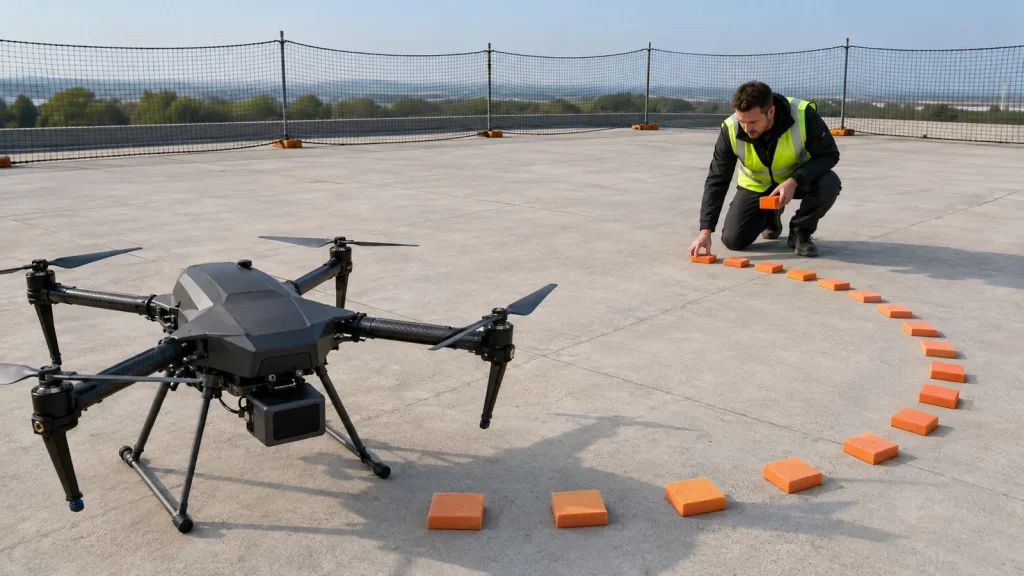
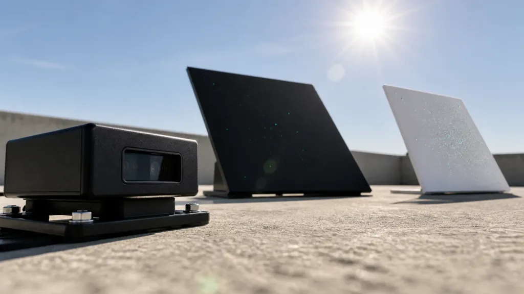
An integrator needs forward collision prevention around rooftop equipment. It chooses a matte white HVAC panel, dark waterproof membrane sample, gray concrete panel, narrow painted pipe, and an angled glossy cover. Tests run at 1 m, the calculated braking threshold, 5 m, and the approved outer bound; each target is measured near-normal and oblique in shade and strong direct sun.
The white panel remains represented in most frames, while the dark oblique sample produces longer invalid bursts in one sun orientation. The team does not average the targets together. It lowers the approved speed for that condition, changes the mounting/host threshold, or excludes the condition until evidence improves. The operational limit follows the weakest critical cell.
For more general ambient-light purchasing tests, read the anti-ambient-light LiDAR pilot guide. For wavelength-specific system questions, see the 940 nm UAV validation guide.
Common bright-scene mistakes
- Calling one clear day “sunlight validation”: measure and band the condition.
- Testing one white wall: include the weakest mission-relevant target finishes and angles.
- Reporting only mean error: valid rate, missed detections, dropout bursts, and false obstacles matter.
- Treating lux as the full spectrum: record it consistently but acknowledge its limits for a 940 nm system.
- Ignoring the optical window: contamination, coating, glare, and enclosure geometry belong in the final-mount test.
- Replacing invalid with far range: preserve unknown and verify safe controller handling.
- Mixing indoor and outdoor maxima: maintain separate qualified envelopes.