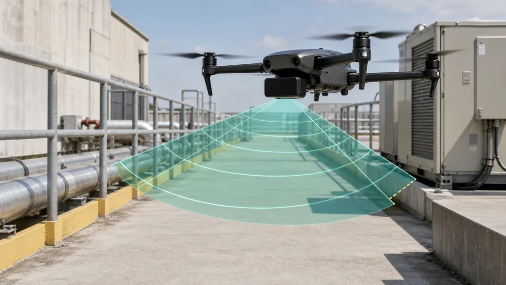
940nm LiDAR often looks like a safe default for compact UAV programs because many solid-state dToF modules, rangefinders, and multizone sensors in this class are small, eye-safe, and easy to package. The validation failure usually happens later, when the team assumes the wavelength label alone proves obstacle-avoidance fitness and skips the harder checks around sunlight, cover windows, field coverage, and how the autopilot will actually consume the data.
This guide is for UAV integration leads and technical buyers who need a practical way to judge whether a 940 nm module deserves bench time and flight-test approval. The goal is not to claim that 940 nm solves every drone-perception problem. The goal is to define the evidence that turns a `940nm LiDAR` shortlist item into a usable obstacle-avoidance workflow.
| Quick answer | Approve a 940 nm LiDAR module for UAV obstacle-avoidance work only after you validate daylight behavior, usable forward coverage, protective-window effects, and the exact autopilot handoff path that will turn depth data into a stop, slow-down, or terrain-aware flight decision. |
|---|---|
| Best fit | Compact drones that need short- to mid-range awareness for obstacle checks, low-altitude hold, or inspection passes where payload, power, and integration time are tightly constrained. |
| Decision rule | If the supplier cannot show repeatable results under relevant light, obstacle geometry, and autopilot data-consumption assumptions, the module is still a bench experiment, not a flight-test-ready component. |
Why 940nm LiDAR is shortlisted for UAV obstacle avoidance
Teams shortlist 940 nm modules because they can be physically compact and because many dToF designs already package the emitter, receiver, and ranging logic into a small integration footprint. That helps when the drone needs a front-facing sensor that does not consume the entire payload budget. The problem is that the shortlist is often made on a headline like "940 nm VCSEL" or "solid-state LiDAR" rather than on scene coverage and flight-behavior evidence.
Current ST documentation for 940 nm dToF modules shows why that shortcut is weak. The latest VL53L9CX datasheet reports characterization in dark and daylight-equivalent conditions, including 5 klx and 40 klx test points, which is a reminder that light environment belongs in the acceptance plan, not in a footnote after purchase. If your team is building a forward obstacle check, the right question is not whether 940 nm sounds standard. It is whether the sensor still delivers usable depth information in the light and geometry your drone will actually see.
Packaging also matters. ST's current cover-glass guidance makes it clear that window quality and crosstalk control affect ranging behavior, so a protective front cover cannot be treated as a neutral mechanical detail. That concern showed up in the Reddit intent set as well, where users were asking whether a LiDAR protector material needs wavelength-specific handling. For a UAV team, that translates into one practical rule: validate the sensor in the housing state you will really fly, not on a bare lab board alone.
If you need a broader UAV context first, start with what drone LiDAR means for UAV integration teams. If your mission is already defined, move directly to coverage, light, and control-loop handoff evidence.
940nm LiDAR validation matrix before flight tests
| Validation question | Why it matters | Pass signal | Red flag |
|---|---|---|---|
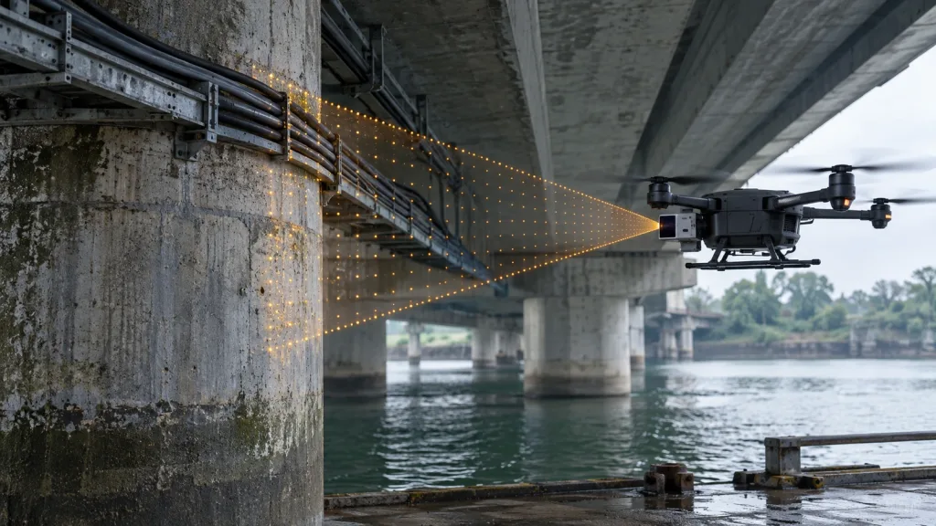
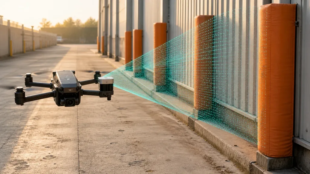
| Does the forward field coverage match the actual obstacle volume? | A compact drone only benefits if poles, rails, cables, and cabinet edges are inside the usable sensing envelope. | The test plan maps coverage against stand-off distance, approach speed, and obstacle width. | The review stops at one FoV number with no scene model. |
| How does the module behave in bright light or rooftop-style glare? | Obstacle-avoidance decisions fail when a sensor is only stable in sheltered indoor conditions. | The supplier shows data under representative daylight or high-ambient-light conditions. | The demo is only a dark-lab clip with no sunlight notes. |
| Has the protective window or front cover been validated? | Optical windows can change crosstalk and usable performance even when the electronics are unchanged. | The evaluation includes the intended aperture, window material, and mounting stack-up. | The flight enclosure is treated as a later mechanical detail. |
| Can the autopilot or companion stack consume the output in time? | The sensor is only useful if its output becomes an actionable distance or avoidance map in the control loop. | The team can explain transport, parsing, rate, and obstacle-map handoff clearly. | The data path depends on vague middleware or undefined custom code. |
| Is the mission really asking for this module class? | Some drones need a bounded forward stop signal or altitude aid, not a more ambitious perception stack. | The team can name the flight behavior that depends on this sensor and the acceptance threshold for it. | The module is being shortlisted because the wavelength and packaging sound modern. |
Exact featured-product reference parameters
The featured Purpleriver module below is used as a factual baseline for a `940nm LiDAR` discussion. It is not proof that wavelength alone determines suitability. It is a concrete reference point for power, field of view, range, and interface trade-offs.
| Product | LiDAR Drone Module – MRP-LD1 Solid-State dToF Sensor |
|---|---|
| Ranging principle | dTOF (Direct Time-of-Flight) |
| Scanning principle | SPAD |
| Emitter | 940nm VCSEL |
| Laser safety | Class 1 (FDA Recognized Eye-Safe) |
| Range | Indoor 0.5-25m; outdoor 0.2-8m |
| Ambient-light resistance | 80Klux |
| Accuracy | 0.2-1m <= +/-3cm; 1-5m <= +/-5cm; 5-8m <= +/-10cm; 8-15m <= +/-20cm |
| Field of view | 60 degrees (H) x 45 degrees (V) |
| Resolution / frame rate | 40 x 30 at 10fps |
| Interfaces | UART / UVC / UDP |
| Software support | Windows / ARM / Linux / Android |
| Power / weight | 5V, 1.2W, 8g |
For a drone team, those numbers matter because they define the integration baseline. A heavier, more power-hungry, or less documented candidate has to justify that extra burden with clearer obstacle-awareness evidence. That is especially important if your mission could also be covered by a simpler forward-facing module plus a disciplined test workflow.
Bench-to-flight validation workflow
- Define the exact flight behavior the sensor must support. Write down the obstacle types, approach speed, stopping distance, and the minimum warning distance or altitude-control margin the aircraft needs.
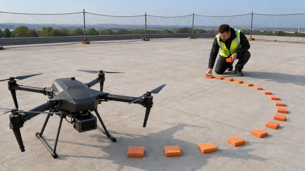
- Map usable coverage against the real scene. Test railings, pipe runs, cabinet corners, netting, and walkway edges at the stand-off distances that matter to your mission, not just against a flat wall.
- Run bright-light and sheltered-light comparisons. If the drone will inspect rooftops, facades, or outdoor utility assets, validate in those conditions instead of extrapolating from a dark workshop.
- Repeat the test with the actual front window or protective cover in place. Do not postpone optical-packaging checks until after you think the sensor has passed.
- Replay the data through your intended host path. Use the transport and parsing method you plan to keep, whether that is `UART`, `UVC`, `UDP`, or a companion-computer pipeline.
- Approve flight tests only after the output can be turned into a stable obstacle signal or distance map in your control stack.
That workflow fits the questions real users are asking. Reddit discussion discovery for `940nm LiDAR` did not point to curiosity about wavelength theory alone. It pointed to practical concerns about which drone setup to buy, whether range claims are good enough in the field, and how LiDAR data becomes useful in a real workflow. Treat those as planning prompts, then verify the answers with primary documentation and your own test evidence.
Before you request a sample, line up the site's documentation resources and sample datasets so the evaluation does not stall after the hardware arrives.
Interface, data, and autopilot handoff planning
The integration question is where many UAV programs quietly fail. ArduPilot's current rangefinder documentation makes a simple point that matters here: obstacle avoidance is not abstract sensor intelligence. It depends on how sensors are mounted and how their coverage is partitioned. A single forward sensor may be enough for one workflow, while broader coverage may require multiple segments or a different sensing architecture entirely. That means the module cannot be evaluated in isolation from the planned mount orientation and field geometry.
PX4's current collision-prevention guide makes the same issue visible from the flight-stack side. It uses an internal obstacle-distance map divided into sectors, which means no-data directions and blind-zone assumptions become operational behavior. A `940nm LiDAR` module can look strong in a static data demo and still fail the flight workflow if its field coverage leaves critical sectors empty or if latency pushes stale distances into the control loop.
That is why interface planning belongs in the article, not in an appendix. Purpleriver's reference module supports `UART`, `UVC`, and `UDP`, which gives UAV teams a concrete baseline for comparing host-side complexity. If you need a refresher on how those data paths change bring-up effort, review UART, UVC, or UDP. If your acceptance run is already unstable, cross-check it against common LiDAR integration issues and how to diagnose them.
For altitude-sensitive work, a forward obstacle workflow also has to stay consistent with low-altitude control expectations. Purpleriver's existing altitude-hold validation guide is useful here because it keeps the team focused on control behavior instead of isolated sensor enthusiasm.
Realistic application case
A facilities-inspection team is building a compact quadrotor to fly along a rooftop service lane and check HVAC equipment. The aircraft needs enough forward awareness to slow or stop before railings, pipe clusters, or cabinet corners, but it also has a tight payload budget and only modest companion-compute headroom.
The team finds a `940nm LiDAR` module attractive because the package is small and the supplier claims the sensor is eye-safe and suitable for outdoor use. The right next step is not a flight day. It is a structured validation pass: test the module against bright concrete, reflective metal edges, and the real protective front window; replay the output through the intended autopilot handoff; then decide whether the sensor produces a reliable stop or warning signal in the distances that matter.
If that workflow passes, the module deserves a flight test. If it does not, the team has still learned something valuable before burning time in the air. For a broader mission checklist, compare the result against drone obstacle-avoidance LiDAR requirements for real-world use.
Common mistakes
- Treating `940nm LiDAR` as a buying answer instead of as a sensor class that still needs mission-specific proof.
- Using only indoor bench data even though the aircraft will fly in bright or reflective conditions.
- Ignoring the front window, bezel, or aperture until the mechanical enclosure is nearly finished.
- Accepting one forward-range clip without mapping which obstacle sectors remain uncovered.
- Comparing vendor range claims without checking host-side transport, parsing, and control-loop timing.
- Starting flight tests before the team can explain how the sensor output becomes a stop, slow-down, or altitude-hold decision.
RFQ checklist
| Ask for | Why it belongs in the RFQ |
|---|---|
| Daylight or high-ambient-light test evidence | Shows whether outdoor or rooftop use is plausible before your own field test starts. |
| Coverage examples tied to your approach geometry | Prevents a generic FoV statement from replacing an obstacle-volume decision. |
| Window or cover-stack recommendations | Reduces the risk that the flown housing behaves worse than the open bench setup. |
| Transport format, update rate, and host assumptions | Reveals hidden integration cost before the sample is approved. |
| Repeatable sample outputs or log files | Lets your team test the same data path it intends to use in the aircraft. |
| Mechanical envelope, power draw, and mounting notes | Protects the payload budget and helps define the actual installation envelope. |
Validate The Flight Workflow, Not Just The Sensor Label
If your UAV team is comparing a 940 nm module for obstacle avoidance or low-altitude sensing, start by defining the obstacle sectors, bright-light conditions, and autopilot handoff you need to prove. That turns the evaluation into an engineering decision instead of a spec-sheet argument.
Purpleriver's compact dToF reference module, documentation, and sample resources can help you build that validation package around known interfaces, field-of-view assumptions, and repeatable test steps. The goal is to request the right sample and approve the right flight test, not to collect another attractive demo clip.
Review the featured module and align your RFQ to the exact light, coverage, and integration questions your aircraft must answer.