0.5–25m indoors and 0.2–8m outdoors long range miniature UAV obstacle avoidance lidar sounds straightforward until a flight team has to prove that a compact module will actually stop or reroute the aircraft before a prop strike, wire hit, or corridor pinch point. The real work is not only checking a headline range number. It is validating coverage geometry, interface timing, host-side parsing, and the exact flight gate where the aircraft is allowed to trust the sensor.
This guide is for UAV integration engineers, program leads, and technical buyers who need a useful validation workflow before flight tests. It uses Reddit-discovered user questions only to identify real concerns such as narrow-space navigation, sensor combination, and recommendation fatigue. The technical guidance itself is grounded in current autopilot documentation, current lidar standards, and the exact featured-product facts available on this site.
| Quick answer | Validate a compact UAV obstacle-avoidance LiDAR in five gates: mission geometry, bench data path, stand-off coverage, autopilot behavior, and controlled flight-lane trials before any open-area deployment. |
|---|---|
| Best fit | Teams evaluating a lightweight dToF module for obstacle-stop, terrain-follow support, and low-altitude UAV perception rather than a survey-grade mapping payload. |
| Decision rule | If your mission depends on onboard obstacle-stop or path-protection behavior, buy and test for coverage, latency, and integration stability first. If it depends on formal mapping deliverables, switch to an aerial-lidar survey workflow instead of forcing a compact obstacle sensor into the wrong role. |
Where this UAV LiDAR category actually fits
The first buyer mistake is mixing two different programs into one shortlist. A compact onboard LiDAR for obstacle avoidance exists to help the aircraft perceive nearby hazards and support control decisions. A survey-grade aerial lidar stack exists to produce defensible geospatial deliverables, which are governed by acquisition, processing, checkpoint, and reporting requirements such as the current USGS Lidar Base Specification and the broader ASPRS positional-accuracy framework.
If your requirement is “do not hit that obstacle while holding a path through a narrow lane,” a miniature onboard module can be the right tool. If your requirement is “deliver a point cloud and accuracy report that a survey client will sign off on,” the program has already moved into a different workflow. That distinction matters because otherwise teams compare compact UAV modules to mapping payloads and never define a realistic validation gate.
Before choosing the test distance, map the complete drone obstacle-avoidance stack from sensing and host processing through decision logic and flight-controller response. That system view prevents a range result from being treated as proof that the aircraft can avoid an obstacle by itself.
The featured MRP-LD1 LiDAR Drone Module is positioned for UAV obstacle avoidance, altitude hold, terrain following, robotics navigation, and short-range 3D perception. This article keeps it inside that truth boundary and shows how to validate it honestly before flight tests.
Decision table
| Buyer situation | What matters most | Better path |
|---|---|---|
| You need the aircraft to slow, stop, or hand off control before hitting nearby obstacles. | Coverage geometry, update timing, integration path, host-side parsing, and repeatable close-range tests. | Compact onboard obstacle-avoidance LiDAR validation. |
| You need terrain-follow support on a light platform with a tight payload and power budget. | Weight, power draw, mounting location, downward/forward sensing geometry, and autopilot behavior under altitude changes. | Compact dToF module with controlled flight-lane validation. |
| You need topographic deliverables, checkpoints, QA reports, or swath-level review. | Survey control, trajectory processing, deliverable QA, metadata, and client acceptance criteria. | Survey-grade aerial lidar workflow instead of a compact obstacle sensor. |
If the team is still debating terms like FoV, frame rate, and point cloud expectations, use the site’s drone LiDAR terminology guide before you request samples.
Exact featured-product parameters
The table below uses only the current featured-product export. It is suitable for evaluation planning because it avoids guessing beyond the approved local product facts.
| Parameter | MRP-LD1 exported fact | Why it matters in UAV validation |
|---|---|---|
| Sensing principle | SPAD-based direct time-of-flight solid-state LiDAR with 940nm VCSEL | Defines the architecture you are validating and the type of onboard depth output you can expect. |
| Range | Indoor: 0.5–25m; outdoor: 0.2–8m | Sets the test envelope for short-range obstacle-stop and low-altitude support, especially outdoors. |
| Resolution | 40×30 | Shapes how finely the module can describe obstacle edges and narrow passages. |
| Frame rate | 10fps | Directly affects how quickly your host stack can react during aircraft motion. |
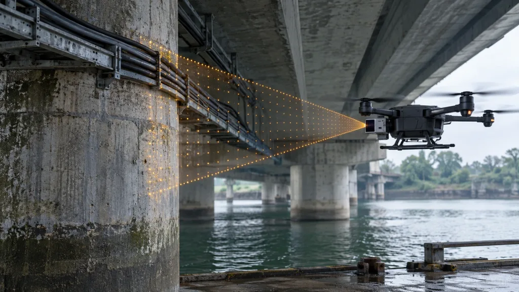
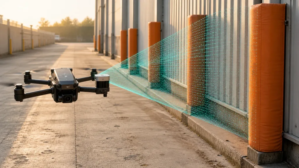
| Field of view | 60°(H) × 45°(V) | Defines the usable coverage wedge you must map against real obstacle geometry. |
| Interfaces | UART, UVC, UDP | Determines how the module reaches your flight controller, companion computer, or replay workstation. |
| Power and weight | 5V, 1.2W, 8g | Useful when endurance, thermal headroom, and mounting budget are constrained. |
| Software support | Windows, ARM, Linux, Android | Lets teams plan bench replay and embedded testing before flight. |
0.5–25m indoors and 0.2–8m outdoors long range miniature UAV obstacle avoidance lidar validation workflow
1. Define the obstacle geometry before you power the sensor
Do not start with “25 meters” as a headline. Start with the actual hazard. Is the problem tree branches on a slow corridor flight, shelving uprights in a warehouse aisle, wires near a rooftop edge, or a narrow gate in a flight cage? A compact LiDAR may have sufficient range and still fail because the approach angle, vehicle speed, or obstacle width makes the usable warning window too small.
Write down four numbers before the first test: vehicle speed, minimum stopping or diversion distance, likely obstacle width, and the stand-off distance at which the autopilot must intervene. Those numbers are more important than the marketing tier of the sensor.
2. Bench-test the entire data path, not only the sensor
A successful bench test means the module is powered correctly, the selected interface is parsed correctly, and the host can convert raw depth output into a repeatable decision stream. The site’s guides to UART, UVC, and UDP choices and Raspberry Pi and Linux integration are useful checkpoints here because they force the team to prove transport and decoding before touching flight code.
If the team cannot log and replay sensor output reliably on the bench, it is not ready for propellers. That is true even if a demo image looks clean.
3. Map the coverage wedge against your stand-off distance
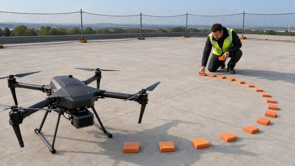
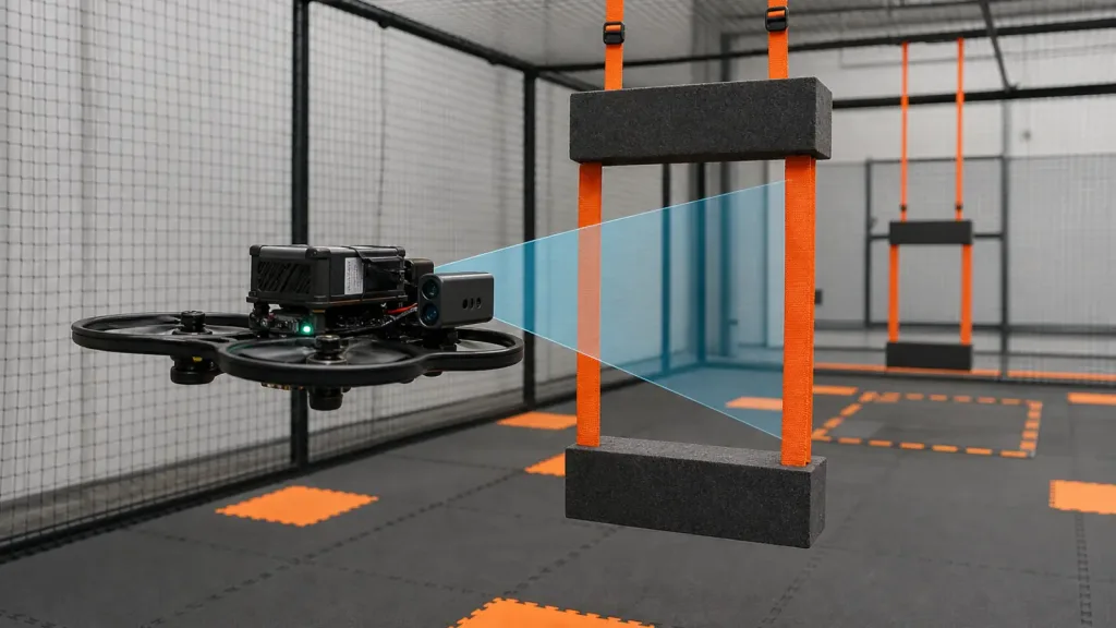
A 60°×45° field of view is helpful only when it is mapped to the obstacle geometry at the distance where action must happen. Build a simple stand-off test with suspended foam blocks, poles, or flat targets placed at the real approach distances used by the aircraft. Record what percentage of the intended lane is visible, where blind edges appear, and whether the intended obstacle occupies enough of the 40×30 depth grid to trigger a stable decision.
This is also where many teams discover they were trying to solve a routing problem with a sensor that only covers a protection wedge. That is not a failure of the module. It is a sign that the system design needs either different placement, different motion limits, or broader sensing.
4. Match the module to autopilot behavior before flight
Current autopilot documentation makes it clear that obstacle prevention is not magic. ArduPilot’s Object Avoidance guidance and RangeFinders Setup Overview both emphasize that rangefinders or proximity inputs must be configured correctly and should be used cautiously. PX4’s Collision Prevention and Distance Sensor guidance documentation likewise frame the feature around specific sensor configuration and obstacle-distance data flow.
In practice, that means you should decide in advance whether the LiDAR is informing a direct flight-controller feature, a companion-computer perception layer, or a replay-and-analysis workflow. Each path has different failure modes, and the test plan must be written for the exact path you choose.
5. Run a controlled flight-lane trial before any open-area mission
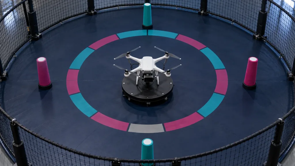
Build a repeatable indoor or netted lane with visible floor markers and soft obstacles. Start with hover or slow-forward tests, then step up to the maximum speed allowed by the risk plan. The trial passes only if the aircraft repeats the same safe behavior under the same geometry, not because it worked once in a clean room.
Use the site’s documentation resources and sample datasets to align what the team sees in logs with what the module is expected to output.
Interface, data, and integration planning
The integration risk on small UAVs is usually higher than the optics risk. A technically capable module can still fail the program if the host path drops frames, delays decisions, or forces the team into a parsing stack it cannot debug. That is why the interface choice belongs inside the article, not in a footnote.
| Integration question | What to verify | Why it matters |
|---|---|---|
| Where does the decision happen? | Flight controller feature, companion computer, or offline replay first. | Defines latency budget and debugging method. |
| What transport path is realistic? | UART, UVC, or UDP based on your compute stack and logging needs. | Prevents teams from choosing a convenient interface that their airframe cannot support cleanly. |
| How will you inspect failures? | Logged raw frames, parsed depth data, and synchronized flight-state notes. | Turns “it didn’t stop” into a diagnosable event instead of a guess. |
| What is the mechanical placement? | Mounting angle, propeller occlusion, vibration path, and protected lens line. | Coverage geometry changes quickly when a small drone body blocks part of the view. |
For teams that also need formal aerial-lidar deliverables, keep a separate requirement track. The USGS data-processing requirements and deliverables guidance show why that workflow is fundamentally different from compact obstacle sensing on a small aircraft.
Realistic application case
A UAV team wants to inspect the inside edge of a greenhouse structure with repeated low-altitude passes and occasional narrow turnarounds. The aircraft is lightweight, the payload budget is tight, and survey-grade mapping is not required. What matters is whether the aircraft can recognize a support member or hanging cable early enough to stop or slow safely.
In that case, the validation sequence should be: bench replay over the intended host path, indoor gate testing with suspended obstacles at the actual approach distance, then slow protected flight in a netted corridor. The team should not start by buying a mapping payload or by assuming one clean obstacle-avoidance demo guarantees safe greenhouse work. A compact module like MRP-LD1 is a realistic candidate because the exported facts cover low weight, low power, short-range depth output, and UAV obstacle-avoidance use, but the program still succeeds or fails on the validation workflow.
Common mistakes
- Using headline range as the main buying criterion instead of the intervention distance required by the aircraft.
- Skipping stand-off geometry tests and assuming one FoV number tells the whole story.
- Trying to use a compact obstacle sensor as if it were a survey-grade aerial lidar system.
- Flying before the team can log, replay, and explain the sensor output on the bench.
- Ignoring interface-path limits until late integration, especially when moving between UART, UVC, and UDP workflows.
- Letting a single successful demo flight replace a repeatable, protected flight-lane test plan.
RFQ checklist
| Ask for | Why it belongs in the RFQ |
|---|---|
| Coverage example at your real stand-off distance | Prevents a generic FoV spec from replacing a real obstacle-lane decision. |
| Raw or replayable sample outputs | Lets your own team verify the host-side path before committing to flight integration. |
| Interface details and host assumptions | Exposes hidden engineering cost before bench work starts. |
| Mechanical placement guidance | Helps avoid propeller occlusion, body shadowing, or avoidable blind zones. |
| Lighting-condition notes for sample evidence | Stops teams from confusing a controlled demo with their real deployment environment. |
| Validation suggestions tied to obstacle-stop or terrain-follow behavior | Keeps the buying discussion anchored to the mission outcome rather than abstract sensing claims. |
Validate The Workflow Before You Trust The Aircraft To It
If your UAV program is evaluating a compact obstacle-avoidance LiDAR, the fastest route to a defensible decision is not a broader shortlist. It is a narrow validation plan that proves coverage, transport, and intervention behavior under the real geometry of your mission.
Purpleriver’s featured MRP-LD1 module gives teams a lightweight SPAD dToF reference point with documented range, interfaces, weight, and supported software environments. Start there, align your bench and flight-lane tests to the exact obstacle problem, and only then expand the system design if the mission still needs more sensing coverage.
Review the featured module and compare it against your own obstacle-stop and terrain-follow validation gates before you request a wider pilot.