Drone Obstacle Avoidance Guides: Run a No-Data Response Drill Before Flight
Most drone obstacle avoidance guides begin with what a sensor can see. An integration team also needs to prove what the aircraft does when the expected obstacle data is unavailable, stale, outside the sensor’s field of view, or deliberately withheld during a supervised test. This guide turns that question into a repeatable preflight drill for a compact UAV evaluation.
Quick answer
Run a low-energy, supervised drill that starts with known obstacle coverage, deliberately creates one documented no-data condition at a time, and records the vehicle’s observed response. Treat the sensor, host software, obstacle-data handoff, flight controller, vehicle dynamics, pilot override, and test boundary as separate checks. A depth sensor is an input to an avoidance system; it is not proof that a complete aircraft will avoid every obstacle.
- Define the directions, ranges, vehicle envelope, and response you intend to test.
- Confirm normal data and coverage in a restrained or low-energy setup.
- Introduce one controlled no-data condition.
- Observe and log the commanded and actual vehicle response.
- Release the configuration only when the evidence matches the written acceptance rule.
1. Start with the system boundary, not a sensor promise
An onboard ranging or depth module can provide measurements. The complete avoidance outcome still depends on mounting, sight lines, target conditions, timestamps, transport, host-side perception, a planner or controller, vehicle tuning, flight mode, and a response that has been validated on the intended aircraft. That distinction is the reason a no-data drill belongs in a real evaluation plan.
For teams using PX4, the current Collision Prevention documentation is a useful implementation reference: it describes obstacle information from connected range sensors or an external source, directional coverage, configured separation, delay, and behavior when data is not available. Read the current documentation for the exact firmware and configuration under evaluation; this article does not replace platform configuration or flight-test approval.
Depth-based avoidance research also evaluates an end-to-end sensing-and-control workflow rather than a sensor in isolation. For example, the peer-reviewed IEEE Transactions on Robotics study on miniaturized-UAV depth-based avoidance combines a multi-zone time-of-flight sensor with a control policy. Its result is not a performance claim for your UAV or for Purpleriver hardware; it is a useful reminder to validate the whole path from measurement to vehicle response.
Before powering the aircraft, write down four boundaries:
- Coverage boundary: directions and conditions for which your test actually has usable obstacle information.
- Response boundary: the command, warning, stop, hold, retreat, or pilot takeover behavior you expect to observe.
- Physical boundary: low-energy setup, propeller policy, tether/cage if appropriate, clear abort path, target placement, and qualified operator roles.
- Evidence boundary: which sensor records, host logs, controller telemetry, and video or observer notes will show whether the acceptance rule was met.
Use the site’s companion guides to plan the normal-case dimensions separately: sunlight and target reflectivity, distance and brake margin, and side-sector validation. A no-data drill does not substitute for those tests.
2. Drone obstacle avoidance guides need a coverage-to-response test table
Choose acceptance rules before the drill. Do not write them after watching a convenient outcome. The table below is a planning tool; your responsible flight-test lead must set the actual limits and abort criteria for the airframe, site, and software release.
| Stage | Controlled condition | Evidence to capture | Example release or abort question |
|---|---|---|---|
| 1. Baseline | Known target inside the intended coverage region; normal sensor stream. | Sensor output, host health indication, obstacle message/log, controller state, pilot input, and vehicle response. | Can the team show that the expected normal data path is alive before a fault is introduced? |
| 2. Directional edge | Move the target to the documented edge of the intended test sector without changing other variables. | Mount orientation, target position, observed data continuity, and actual aircraft behavior. | Is the boundary recorded as an observed condition rather than assumed from a drawing? |
| 3. Controlled no-data input | At low energy, remove or withhold one defined data input using the approved test method. | Time of transition, fault/health indicator, controller mode/state, command response, and operator action. | Did the response meet the prewritten rule, or did the team abort safely? |
| 4. Recovery | Restore the normal input only after the aircraft is stable and the test lead authorizes recovery. | Recovery timestamp, any warning clearance, data continuity, and post-test inspection note. | Did recovery require an unexpected reset, mode change, or operator intervention? |
| 5. Repeatability | Repeat only the approved scenario with one controlled variation, such as orientation or transport path. | Version IDs, configuration delta, comparable log windows, and deviations. | Is there enough evidence to decide whether to expand, revise, or stop the evaluation? |
Keep the test purpose narrow. A successful response in one supervised condition does not establish collision-free operation in all directions, speeds, lighting, target materials, or flight modes.
3. Use a compact dToF LiDAR as an evaluation input—not a complete avoidance system
The MRP-LD1 Drone LiDAR Sensor can be evaluated as one depth-and-point-cloud input for UAV obstacle sensing. Its supplied product information states that it provides depth images and 3D point-cloud data, while the host processor, perception logic, planning, flight controller, and validated response remain part of the complete system.
| Documented field | Supplied value | How to use it in a no-data drill |
|---|---|---|
| Ranging principle / scanning principle | dToF / SPAD | Record the sensor and software versions used; do not infer system-level avoidance performance from the sensing method. |
| Documented ranging capability | 0.5–25 m indoors; 0.2–8 m outdoors | Choose targets and an initial low-energy test geometry inside the documented baseline, then validate the intended scene. |
| Field of view | 60° (H) × 45° (V) | Map the installed view to the test direction; it does not prove coverage beyond the mounted field. |
| Resolution / frame rate | 40 × 30 / 10 fps | Capture the observed update behavior and timing in the actual host pipeline rather than assuming an aircraft response. |
| Output / interfaces | Depth and point-cloud output; UART, UVC, UDP | Define the selected transport, health signal, and logging point before fault injection. |
| Mass / power consumption | 8 g / 1.2 W | Record the installed configuration and power arrangement for the tested aircraft; assess vehicle effects in the intended integration. |
The product listing also gives a 940 nm VCSEL, Class 1 laser-safety description, 80 Klux ambient-light resistance, and listed host support for Windows, ARM, Linux, and Android. Use the supplied product page and requested documents for the exact evaluation configuration. Do not turn catalog values into promises about an installed aircraft, mission range, or stopping behavior.
4. Illustrative application case: a supervised indoor corridor drill
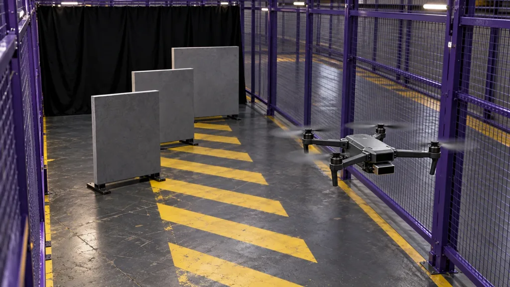
Consider an integration team preparing a compact multirotor for a warehouse-aisle inspection prototype. The team creates a controlled indoor corridor with a stable target panel in the forward test region, a clearly marked retreat direction, a safety boundary, and an observer responsible for the abort call. The vehicle begins restrained or at the lowest practical energy state permitted by the test lead.
First, the team records normal depth/point-cloud output at the selected host interface and confirms that the downstream obstacle-data path reports the expected healthy state. Next, it introduces one pre-approved no-data condition—such as a controlled host-side input hold or an approved disconnect method—without changing the target, airframe configuration, or operator roles. The useful outcome is not “the drone is safe.” It is a time-aligned record of what the sensor path, host, controller, and operator actually did under one defined condition.
After a safe recovery, the team compares that record with the written acceptance rule. If the rule and observation disagree, the result is a revision task, not an invitation to widen the test envelope. This approach keeps the test honest and makes it easier to communicate evidence to an engineering manager or procurement reviewer.
5. Make the sensor-to-controller handoff observable
A no-data drill is only useful if you can locate the break. Plan named observations at every handoff: sensor output, selected interface, host parser or perception process, obstacle-data message, controller state, and vehicle response. The site’s LiDAR sensor data-contract guide can help turn that plan into an integration checklist.
If your platform uses PX4, consult its current ObstacleDistance message reference and Collision Prevention documentation alongside the firmware source and release notes that govern your build. Keep platform-specific details in the test record: firmware version, parameter export, frame/orientation definition, source timestamp behavior, selected message path, and relevant logs. Do not copy a setting from a web page into an aircraft without its own configuration review.
Minimum evidence package
- Airframe, sensor, host, and flight-controller identifiers plus firmware/software versions.
- Mounting orientation, intended sensing region, target geometry, and physical test boundary.
- Chosen interface and a definition of normal, degraded, and no-data states.
- Time-aligned sensor/host/controller logs and the exact pilot or autonomous command issued.
- Observed vehicle state, operator intervention, abort reason if any, and a configuration-change record.
6. Common mistakes that make a no-data drill misleading
- Calling an uncovered direction “clear.” No measurement is not a verified free path. Label the state explicitly in the test design.
- Changing several variables at once. Moving the target, altering speed, updating software, and withholding data in one run makes the evidence hard to interpret.
- Testing only the sensor. A healthy sensor stream says little about host timing, message transformation, controller logic, or actual vehicle response.
- Using product range as a flight envelope. The documented MRP-LD1 baseline is a starting point for evaluation; target, angle, ambient light, mounting, motion, and the complete vehicle must be validated in the intended scene.
- Skipping recovery and abort notes. A run that needs an unexpected reset or pilot intervention is valuable evidence, even when the team decides not to continue.
- Overstating the result. One controlled drill supports one documented conclusion. It does not certify an aircraft or demonstrate every environment.
7. RFQ and evaluation checklist for the next step
Before requesting a sample, project-specific quote, or integration review, prepare this short evidence brief:
- Target platform, payload/mounting concept, intended application, and working-distance envelope.
- Indoor or outdoor scene, target materials, expected ambient conditions, and intended flight directions.
- Host system and preferred MRP-LD1 interface: UART, UVC, or UDP.
- Which output you need to evaluate: depth data, point cloud, or both.
- Test boundary, desired log artifacts, sample quantity, and expected project timing.
- The exact question your no-data drill must answer, plus the required operator-abort rule.
This level of preparation gives a supplier or internal engineering team the context needed to discuss documents, SDK resources, sample data, an evaluation sample, or a project-specific quote without assuming unverified vehicle behavior.
Frequently asked questions
Is an MRP-LD1 module a complete drone obstacle-avoidance system?
No. It supplies documented depth images and 3D point-cloud data for host-side evaluation. The host processor, perception logic, planning, flight controller, and validated vehicle response are still part of the complete system.
What does “no data” mean in this drill?
Define it for the specific handoff under test: no expected sensor output, an explicitly unhealthy host input, a missing obstacle-data message, or another approved condition. Record that definition before running the drill.
Can I test an uncovered direction by simply flying toward it?
Do not treat an untested direction as clear. Use a supervised, low-energy setup with written boundaries and an abort plan. The response to missing coverage depends on the complete aircraft configuration.
Which MRP-LD1 interface should I use?
The documented interfaces are UART, UVC, and UDP. Select the one your host can validate and log reliably, then document the chosen path in the test record.
Does the documented 0.2–8 m outdoor capability establish my flight range?
No. It is a product baseline. Actual use depends on the target, ambient light, angle, mounting, motion, host integration, and vehicle behavior; validate the intended scene.
Why include a controller-specific reference such as PX4?
It provides a current first-party example of how an autopilot can consume obstacle information and treat coverage, delay, and unavailable data. Use only the documentation and configuration applicable to your own release.
What should I log during the transition to no data?
At minimum, capture timestamps, sensor output or health, host process state, obstacle-data handoff, controller state, commanded motion, observed motion, and any operator intervention.
Can this drill prove that the UAV will avoid every obstacle?
No. It evaluates one defined condition. Broader claims require a controlled validation program covering the relevant directions, speeds, targets, environments, modes, and system configurations.
What should I send when requesting an evaluation sample or quote?
Share the platform, application, working distance, scene, host system, preferred interface, sample quantity, expected timing, and the evidence you need from the proposed integration test.
Turn the drill into an evaluation conversation
If your team is evaluating a compact dToF input for UAV obstacle sensing, bring the coverage map, host interface, intended test scene, and no-data response question to the conversation. Review the MRP-LD1 product details, then request product documents, SDK resources, sample data, an evaluation sample, or a project-specific quote with your test brief attached.