Mobile-robot integration guide
A robot obstacle avoidance dToF sensor can provide a compact depth or point-cloud input, but it does not by itself decide whether the robot should slow, stop, turn, or continue. Before a pilot, give the sensor one bounded job: produce a trustworthy near-field observation stream with an explicit frame, usable region, freshness rule, and handoff to the navigation stack.
This guide helps an AMR or indoor-mobile-robot team decide where that input belongs alongside stereo or RGB vision, then turn the decision into a testable integration contract.
Quick answer
Use a compact dToF depth module as a near-field observation source when the team can state what volume it covers, how its depth/point-cloud output is converted, which returns may mark or clear an obstacle representation, and what happens when data is stale. Keep semantic identification, path planning, motor control, and the validated response as separate responsibilities. In other words: evaluate the data contract before calling the assembly “obstacle avoidance.”
Give the robot obstacle avoidance dToF sensor one bounded job
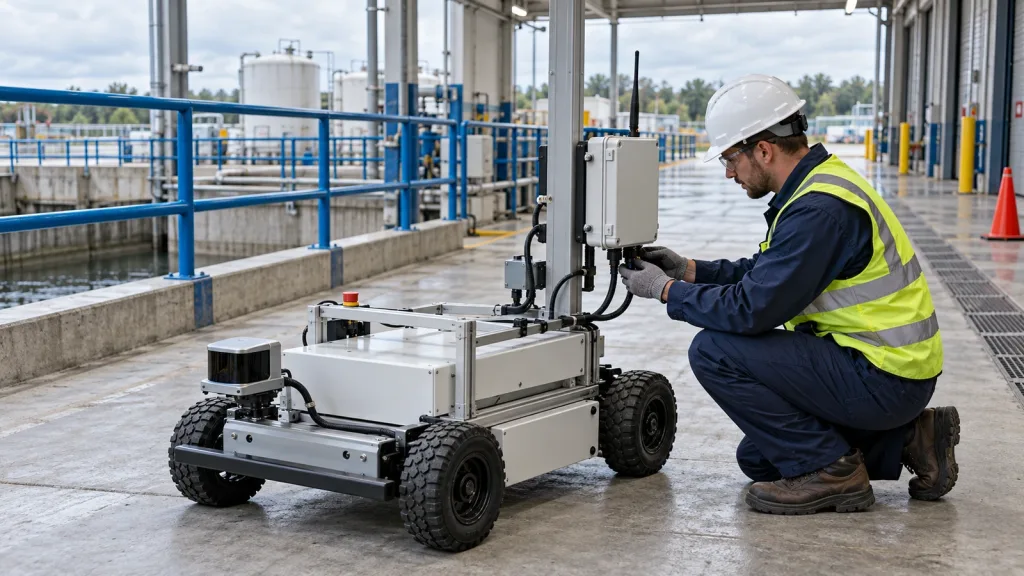
The useful first question is not “Can this module avoid obstacles?” It is “Which observation does the rest of this robot need from this module?” A 40 × 30 depth grid or its derived 3D points can be useful for an intentionally limited region in front of a robot. That output still needs mounting geometry, timestamps, filtering, a host-side representation, and a documented response path.
For a concrete implementation reference, the Nav2 obstacle-layer documentation exposes exactly the questions an integration contract should answer: observation source, message topic, sensor frame, min/max range, height bounds, and whether observations mark or clear space. Nav2 is an example, not a requirement; use the equivalent controls in the robot’s own middleware or navigation stack.
That division keeps the evaluation honest. A depth module may make a bounded spatial measurement available. It does not independently establish a safe stopping distance, validate a controller, classify a person or pallet, or replace a system-level hazard analysis.
Decision chart: choose the responsibility before choosing the claim
| Team need | Useful input role | Evidence to collect | Do not assume |
|---|---|---|---|
| Bound a near-field volume in front of a low-speed robot | dToF depth or derived point cloud used as an obstacle observation source | Mounting frame, usable volume, target set, timestamp/freshness behavior, and event log | That a depth frame is already a route decision or a safety function |
| Identify object type, signage, or free-space context | Vision or a separately validated perception pipeline | Representative images, label policy, confidence handling, and failure cases | That depth alone provides semantic identity |
| Move around a detected object | Planner/controller consuming a defined obstacle representation | Marking/clearing rules, latency budget, brake/turn behavior, and replay traces | That sensor range equals the vehicle’s validated response distance |
| Operate in changing light or materials | Scenario-specific test matrix across the selected sensing stack | Material, angle, motion, ambient-light condition, and outcome for every run | That one bench result generalizes to every target or environment |
Current peer-reviewed SPAD dToF literature describes system trade-offs involving ambient light, reflectivity, pile-up, and interference; that is a reason to test representative scenes, not a basis for assigning unmeasured performance to a particular module. See this 2026 review of SPAD-array dToF LiDAR design for the underlying context.
MRP-LD1 parameters to place in the integration record
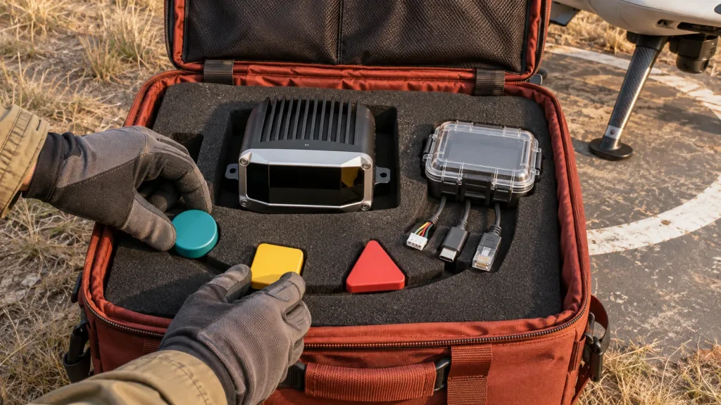
If the evaluation uses Purpleriver’s Featured MRP-LD1 Drone LiDAR Sensor, copy the supplied parameters into the project record rather than transcribing them from memory. The table below is a product-data reference, not a system-performance guarantee.
| Supplied parameter | MRP-LD1 value | Integration question |
|---|---|---|
| Ranging / scanning principle | Direct time-of-flight; SPAD | Which host representation will consume the depth or points? |
| Emitter / laser safety listing | 940 nm VCSEL; Class 1 (FDA recognized eye-safe) | Which project-specific optical and operating review is required? |
| Documented ranging capability | Indoor 0.5–25 m; outdoor 0.2–8 m | What smaller project operating volume will be tested first? |
| Documented ambient-light resistance | 80 Klux | Which real lighting conditions and target materials must be logged? |
| Documented accuracy bands | 0.2–1 m ≤ ±3 cm; 1–5 m ≤ ±5 cm; 5–8 m ≤ ±10 cm; 8–15 m ≤ ±20 cm | Which distance bands matter to the pilot, and how will they be checked in the intended scene? |
| Field of view / resolution / frame rate | 60° H × 45° V; 40 × 30; 10 fps | Where are the physical and effective blind sectors after mounting? |
| Outputs and interfaces | Depth images and 3D point-cloud data; UART, UVC, UDP | What converter, framing, timestamp, and health status are required at the host boundary? |
| Host support / electrical / mechanical | Windows, ARM, Linux, Android; 5 V; 1.2 W; 8 g | Can the chosen host, power path, harness, and mount be observed during the pilot? |
For complementary capture and replay planning, see the site’s LiDAR SDK Windows Linux validation guide and dToF LiDAR evidence FAQ.
Build the near-field observation contract
Write the contract before tuning a planner. It should be short enough to attach to a pilot ticket, yet concrete enough that a failed replay exposes which handoff needs attention.
- Mounting frame: name the physical sensor frame, measure its rigid relationship to the robot body, and record the orientation. Repeat the measurement after a mount change.
- Observation volume: declare a conservative first-test region inside the supplied field of view and documented range. State the areas excluded by bumper geometry, floor returns, cabling, or occlusion.
- Message boundary: choose the source output—depth image or derived points—and document conversion, timestamp origin, units, confidence handling, and frame identifier. Preserve a raw capture for replay.
- Obstacle policy: define which returns become obstacle evidence, which regions are ignored, and whether a valid observation can clear an old mark. Nav2’s mapping/localization guide illustrates the same decisions for `PointCloud2` sources, including marking, clearing, and range boundaries.
- Freshness and fault behavior: set an observable stale-data condition, disconnect/reconnect check, and log field. The controller’s behavior when the input is missing must be designed and tested by the robot team.
- Acceptance replay: save the input, transform state, obstacle representation, commanded motion, and test outcome with the scenario conditions. A successful-looking screenshot alone is not enough evidence.
A useful companion page is the robotics-perception LiDAR pilot-cell acceptance plan. For broader screening criteria, use the solid-state LiDAR selection scorecard.
Illustrative application case: a compact robot test lane
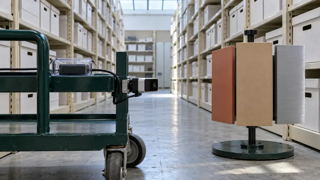
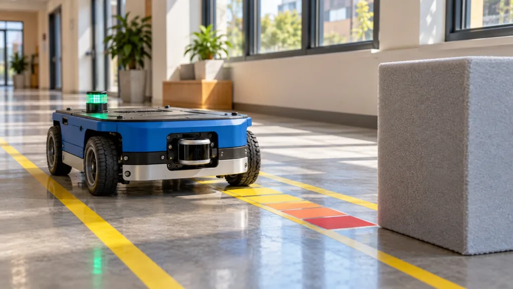
Scenario: A team is preparing a low-speed indoor pilot for a compact material-handling robot. The module is mounted at the front of the chassis. A foam pedestal and a matte carton represent two differently shaped near-field targets. This is an example workflow, not a recorded product test result.
The team first records the sensor-to-body transform and tapes a short, straight test lane. For each run, it logs target material, offset angle, distance band, ambient condition, robot speed, raw sensor capture, converted obstacle input, and commanded response. It repeats the run with an intentionally stale stream and with the sensor path blocked. The review asks four separate questions: Was there a valid observation? Was it transformed and filtered as intended? Did the obstacle representation change as intended? Did the robot exhibit the response the team had separately specified?
This sequence makes it possible to diagnose a miss without blaming “the LiDAR” generically. It also creates evidence that can be compared with target-material work in the site’s dark-tote and low-contrast-edge validation guide.
Common mistakes that hide the real integration problem
- Calling a depth image “avoidance.” Keep observation, perception, planning, control, and validation as named, separately testable stages.
- Testing only a flat, high-contrast target. Build a target/material/angle/light matrix that resembles the pilot environment.
- Leaving the frame implicit. A correct point set in the wrong coordinate frame can create a misleading obstacle location.
- Clearing without a documented policy. Distinguish a genuinely observed free ray from a dropped, stale, or filtered observation.
- Using a range figure as a stopping claim. Supplied sensing capability and the robot’s validated response envelope are different records.
- Skipping replay data. Retain raw input and the transformed/consumed result so a pilot incident can be reconstructed.
RFQ and evaluation checklist
- State robot type, chassis geometry, mounting location, working distance, speed envelope, and indoor/outdoor condition.
- Specify whether the host needs depth, point-cloud data, or both; name the preferred UART, UVC, or UDP path and host platform.
- Request the applicable interface documentation, data-format examples, SDK resources, and a sample-data capture for the intended integration path.
- Provide the target materials, expected angles, ambient-light conditions, and occluders for the first test matrix.
- Define the frame convention, timestamp/freshness expectation, logging fields, and replay owner before hardware arrives.
- Record the intended obstacle-marking/clearing policy and the separately owned controller-response test.
- Ask for a sample or project-specific quote only after the team can share the evidence plan.
Turn the integration question into an evidence package
If you are evaluating MRP-LD1 for a mobile robot, share the mounting concept, target distance, environment, host platform, preferred interface, and the observation-contract questions above. Purpleriver can provide the documented product information, SDK resources, sample data, an evaluation sample, or a project-specific quote for the team’s review.