Quick answer: A 5G LiDAR module should be evaluated as two separate layers: a depth sensor that produces data and a 5G communications path that moves selected data to another system. Do not assume that a LiDAR module contains a modem, SIM/eSIM, antenna, carrier approval, or a promised latency simply because a project uses 5G. First verify the sensor output, host interface, power and scene fit; then validate the network path under the actual data and response requirements.
When an integration lead searches for a 5G LiDAR module, the practical question is usually not whether a radio label sounds advanced. It is whether a compact depth sensor can supply a useful local data stream while a separate communications architecture supports the pilot. That distinction prevents a costly mistake: treating a sensor specification as proof of end-to-end sensing, networking, decision logic, and field response.
What does “5G LiDAR module” actually mean?
It is a search phrase, not enough information to define a product architecture. In a real project, it may mean a LiDAR sensor mounted on equipment that also has a 5G-connected gateway; a sensor plus host processor whose results are forwarded over a cellular link; or a request for a device with an integrated radio. Those are materially different requirements. 3GPP TS 23.501 defines the system architecture for a 5G System; it is useful context for treating the network as an architecture layer rather than assuming every connected sensor is itself a 5G device.
For a technical buyer, the first useful answer is therefore a boundary statement: name the depth source, name the host that receives and interprets it, and name the device that connects to the mobile network. If the supplier documentation does not explicitly state an embedded radio, do not put “integrated 5G” on the requirements sheet.
Use a two-layer screen before committing to a pilot
| Decision layer | Question to answer | Evidence to request or measure | Do not conclude yet |
|---|---|---|---|
| Depth sensing | What data leaves the sensor, through which documented interface? | Interface documentation, representative output, supported host environment, and a bench capture. | That an application is safe, autonomous, or network-ready. |
| Host processing | Which host converts depth or point-cloud data into the project’s usable signal? | Data contract, timestamp policy, error handling, processing location, and a replay test. | That the sensor alone makes vehicle or production decisions. |
| 5G transport | What data must cross the radio link, and what happens when it does not? | Gateway or modem specification, carrier/network plan, payload definition, loss handling, and measured pilot logs. | That “5G” automatically meets a latency, availability, or coverage target. |
| Application response | Who owns the alarm, stop, route change, or operator workflow? | System hazard review, controller behavior, fallback state, and a representative-scene validation plan. | That a LiDAR output is a complete avoidance, inspection, or safety system. |
This split is also a sound measurement habit. NIST’s 2025 work on methods to evaluate 3D LiDARs identifies factors spanning sensor design, interfaces and software, algorithms, targets, and operating environment. A pilot should record those conditions instead of crediting every observed result to either the sensor or the network label.
MRP-LD1 published baseline: useful sensor facts, not a 5G claim
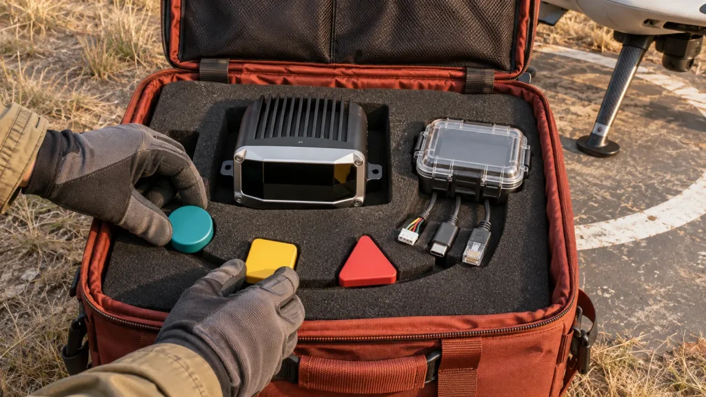
The Featured-product export identifies the MRP-LD1 Drone LiDAR Sensor as a solid-state SPAD dToF module for embedded depth-perception evaluation. Its published interfaces are UART, UVC, and UDP, with software support listed for Windows, ARM, Linux, and Android. Those facts help frame a local integration discussion. They do not document an embedded 5G modem, a radio interface, carrier compatibility, or a 5G performance commitment.
| Ranging principle / scanning principle | dToF / SPAD (Single-Photon Avalanche Diode) |
|---|---|
| Wavelength / laser safety | 940 nm VCSEL / Class 1 (FDA Recognized Eye-Safe) |
| Published ranging capability | Indoor: 0.5–25 m; outdoor: 0.2–8 m |
| Ambient-light resistance | 80 Klux |
| Field of view / resolution / frame rate | 60° (H) × 45° (V) / 40 × 30 / 10 fps |
| Output and interfaces | Depth images and 3D point-cloud data; UART, UVC, UDP |
| Power / weight / supply | 1.2 W / 8 g / 5 V |
| Software support | Windows, ARM, Linux, Android |
| Operating temperature | -20–60 ℃ |
Use the values above as a candidate baseline, then test the intended scene. The export does not state physical dimensions, mounting-hole details, connector pinout, enclosure requirements, timing/latency commitment, or 5G-radio capability. Request those items where they matter instead of filling the gap with assumptions.
Realistic application case: a connected inspection pilot without false coupling
Illustrative workflow: compact depth sensing on a mobile inspection trolley
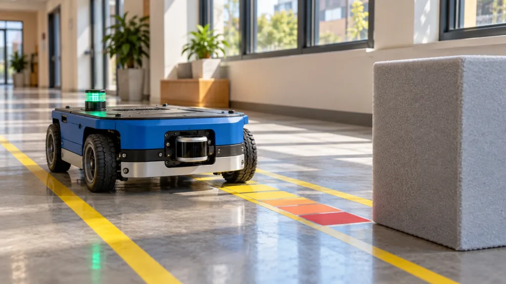
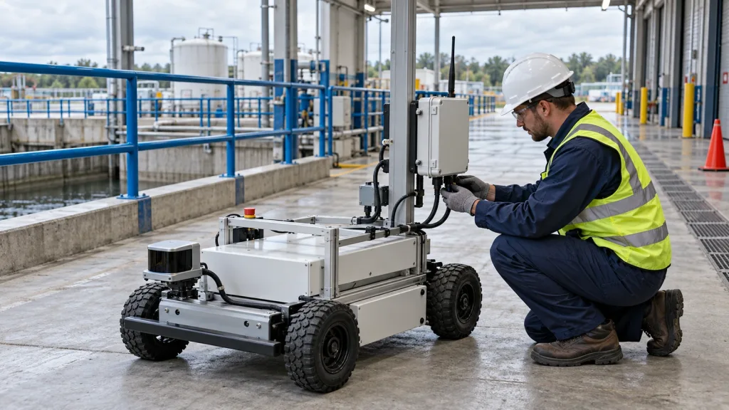
Consider an integration team preparing an indoor-to-covered-loading-area pilot. The sensor is installed to observe a defined inspection zone. A local host receives depth or point-cloud output, records representative sessions, and applies the project’s own event rules. A separate gateway may send selected records, health information, or approved application events over the project’s communications path. The team first proves that the local sensor-to-host capture is stable; it then evaluates network transport separately, including what the host does during a link interruption.
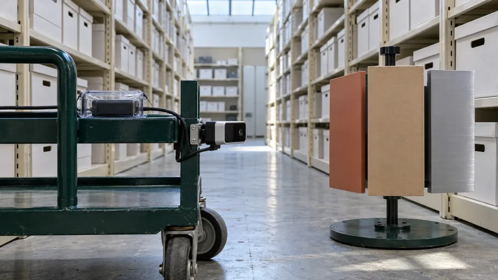
On a covered industrial inspection loading-bay setup, a technician should also record the physical cable handoff between the compact solid-state dToF LiDAR module’s local equipment and a separate gateway enclosure. This does not make the sensor a 5G device; it makes two independent integration points visible to the team. The workflow is deliberately conservative: it does not claim that MRP-LD1 is a completed connected-inspection solution, and it does not transfer results from one site to another. It creates evidence that helps a buyer decide whether to continue with the sensor, host, gateway, and application design.
Design the data handoff before you design the 5G story
Start with a small, reviewable data contract. Define the local input interface, the data unit the host receives, the confidence or validity information available in the documented output, the timestamp owner, and the behavior for invalid or missing data. The site’s UART, UVC, or UDP interface guide and sensor-to-controller data-contract guide are useful starting points for the local side of that discussion.
Then decide what crosses the network. Raw sensor output, derived geometry, event records, diagnostics, and software updates have different payload, timing, retention, and failure-handling needs. The safe answer is not a generic bandwidth number; it is a pilot measurement tied to the actual host software, network path, target behavior, and fallback action. NIST’s 3D-sensor evaluation work for manufacturing automation is another reminder to state the measurement task and conditions when comparing 3D sensing results.
For a UAV or robot project, keep responsibility explicit: a depth module supplies sensor data; a host may interpret it; the application or controller defines a response; and a network link may transport selected information. For local integration work, review the site’s compact dToF evaluation workflow before extending the architecture into a field pilot.
Common mistakes that make a connected-depth pilot hard to trust
- Buying the phrase rather than the interface: asking for a “5G LiDAR module” without saying whether the radio belongs in the sensor, host, or gateway.
- Calling a sensor an autonomous system: leaving host logic, controller behavior, and validation unassigned.
- Testing only the happy path: collecting one clean bench stream but not documenting target material, light, mounting, motion, environmental conditions, or loss-of-link behavior.
- Sending everything by default: choosing a network payload before deciding what the remote system actually needs.
- Inventing missing product details: treating an unpublished connector, latency, antenna, or 5G feature as if it were documented.
RFQ and evaluation checklist
- Name the application, working zone, representative targets, lighting, motion, and indoor/outdoor conditions.
- State whether the request is for a LiDAR module, a host-ready depth subsystem, a gateway-connected pilot, or a complete system integration.
- Choose the local interface to evaluate and identify the host operating environment.
- Ask for only documented product materials; list any required physical, connector, firmware, or timing information that remains unconfirmed.
- Define what data remains local and what information, if any, must traverse the network.
- Specify how the host and application behave when data is invalid, delayed, or unavailable.
- Set pass/fail observations for the representative scene and retain logs that explain the setup.
- Request product documents, SDK resources, sample data, an evaluation sample, or a project-specific quote only after the evidence package is clear.
Build the evidence package before the connected pilot
If you are screening a compact depth module for a UAV, robot, AR/VR, or inspection program, start with the published MRP-LD1 baseline and share your target platform, scene, host system, preferred local interface, and the role you expect a separate network path to play. Purpleriver can provide product documents, SDK resources, sample data, an evaluation sample, or a project-specific quote.
Discuss an evaluation with Purpleriver or review the documentation resources.