UAV integration guide
Drone LiDAR Solutions: Define the Sensor-to-Flight-Controller Evidence Package
A compact depth module can be a sensible starting point for a UAV evaluation, but it does not by itself establish obstacle avoidance, terrain following, or a flight-controller interface. The useful way to assess drone lidar solutions is to make the handoff boundary visible: what the sensor measures, what the host validates, and what the aircraft control stack is actually configured and tested to use.
Quick answer
A credible drone LiDAR solution is an evidence package, not a single specification sheet. First document the installed sensor view and output; next prove the host-side interpretation, timing, and invalid-data handling; then separately verify the controller input and the aircraft response. If any of those three records is missing, treat that layer as unproven. This keeps a compact sensor evaluation useful without presenting a module as a complete flight-safety system.
Drone LiDAR Solutions Need Three Separate Proofs
For an integration lead, the buying decision becomes clearer when the system is split into a sensing layer, a host/perception layer, and a flight-control layer. A module can be appropriate for the first layer while the other two still require design and validation work. The table is a decision chart: it says what to collect, not what any product automatically does.
| Layer | Question to close | Evidence to retain | Do not infer |
|---|---|---|---|
| Sensor and installation | What part of the scene is in view from the installed location? | Mount photos, orientation record, representative captures, and the documented operating baseline. | A published field of view or range is not a proof of installed coverage. |
| Host and perception | How are frames accepted, rejected, transformed, and timed? | Raw samples, parsing notes, validity rules, coordinate convention, and stale-data behavior. | Depth or point-cloud output is not a control decision. |
| Flight controller | Which declared input reaches the configured controller path, and what happens when it is absent? | Controller configuration, message trace, health/fault observation, and controlled test record. | A host can format data without proving aircraft behavior. |
This division answers a recurring buyer concern: the hard part is often not whether a sensor can produce a measurement, but whether the responsibility for interpreting that measurement and acting on it has been made explicit. Start with the site’s practical drone LiDAR integration overview, then use this article to turn the broad concept into reviewable evidence.
Use Product Facts as a Bounded Starting Point
The featured MRP-LD1 Drone LiDAR Sensor is documented for embedded depth-perception evaluation. Its facts are useful for scoping a bench or installed trial; they are not a claim of a native autopilot driver or complete avoidance function.
| Documented MRP-LD1 item | How to use it in an evaluation |
|---|---|
| Solid-state SPAD dToF, 940 nm VCSEL | Record the sensing approach in the design file; do not substitute it for installed-scene evidence. |
| 0.5–25 m indoor and 0.2–8 m outdoor ranging baselines | Choose representative distances, then test the target, ambient light, angle, mounting, and motion that the intended aircraft will encounter. |
| 60° × 45° field of view; 40 × 30 resolution; 10 fps | Check the actual mounted view and the host’s capture and retention plan. |
| Depth and point-cloud output; UART, UVC, and UDP | Select one documented acquisition path and define the conversion or parsing responsibility on the host. |
| 8 g, 1.2 W at 5 V | Use these supplied module facts in the platform review; document the complete installed power and mounting arrangement separately. |
The product record lists UAV obstacle avoidance and altitude-hold evaluation among its intended application groups. Actual usable performance still depends on the scene and installation, so the approval record should say exactly what was tested instead of promising a universal operational distance.
Build a Sensor-to-Controller Boundary Worksheet Before You Buy
A one-page worksheet prevents different teams from assuming that somebody else owns the integration gap. Give every row an owner and a file or test reference.
- Scene and mount: State the intended direction, protected mounting location, physical obstructions, target classes, and a photo of the installed view.
- Sensor output: Identify the chosen MRP-LD1 output path and retain a representative depth or point-cloud capture. Do not call it flight-controller data unless that translation is actually implemented.
- Host contract: Specify the frame convention, timing source, validation conditions, missing-frame rule, and the exact team that owns the parser.
- Controller boundary: Name the interface, orientation declaration, allowed measurement limits, and the controller configuration to be tested.
- Fault boundary: Define what the host reports when data are late, invalid, or outside the intended scene, and how that condition is observed in a controlled evaluation.
- Acceptance record: Store the configuration revision, test conditions, raw samples, and the result of each controlled test. A screenshot-free record is easier to review and repeat.
For teams deciding among transport options, the site’s UART, UVC, or UDP guide is a useful starting point. It should be followed by a project-specific test of the selected path, rather than an assumption that every physical connection is already a controller input.
Plan the Data and Flight-Control Handoff Explicitly
If a host is designed to turn a validated range result into a flight-stack message, the message semantics need their own review. The primary MAVLink DISTANCE_SENSOR definition includes a timestamp, minimum, maximum, and current distance, sensor ID, orientation, field-of-view fields, and a signal-quality field. That is a useful checklist for a proposed handoff. It does not mean a depth module natively emits MAVLink or is accepted by every controller.
Likewise, the current PX4 distance-sensor documentation is valuable because it frames a rangefinder as a configured and tested part of a broader system. Use it to formulate the right controller-side questions—mount offset, orientation, delay, noise treatment, health reporting, and controlled tests—without claiming that the Featured module has a particular PX4 driver.
Where a team needs a project-level definition, connect this worksheet to its existing LiDAR sensor data-contract guide. The clean handoff is not “the module is connected”; it is “the documented host rule produced this declared input under these recorded conditions.”
Illustrative Case: A Perimeter-Inspection UAV Evaluation
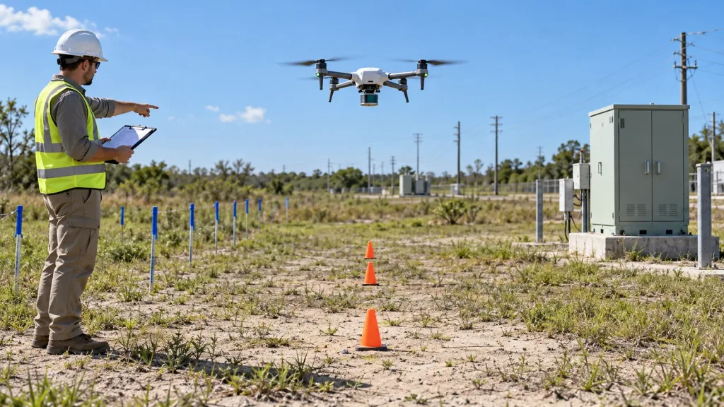
Consider a team evaluating a compact depth module for a slow, low-altitude perimeter-inspection aircraft. This is an example of an evaluation workflow, not a claim about flight performance. The team mounts the module where its intended sector is physically unobstructed, records representative target and background captures through one selected interface, and lets a host computer label each capture accepted, rejected, or stale.
Before any controller behavior is assessed, the host team documents the body-frame orientation and the limits it intends to declare. A separate controller owner then checks the chosen input path and records what happens during deliberately invalid or missing data. The deliverable is an evidence packet containing the mount record, raw samples, host rules, controller configuration, and controlled observations. It is deliberately more useful than a single claim that the aircraft “has avoidance.”
When the broader mission needs an application overview, connect the evaluation to the site’s UAV navigation and obstacle-avoidance solution page. Keep mission messaging distinct from the evidence required to approve an individual integration.
Common Mistakes That Weaken a Drone LiDAR Evaluation
- Calling a module a complete solution. A sensor supplies measurements or data; perception, planning, controller configuration, and validated response remain system work.
- Testing only a nominal target. A useful record includes relevant target surfaces, angles, background, ambient conditions, mounting, and vehicle motion.
- Leaving orientation implicit. A correct distance value can still be unusable if its physical direction and frame convention are not declared.
- Discarding raw evidence. Keep representative captures and configuration revisions so a later review can distinguish a measurement issue from a parser or controller issue.
- Assuming an interface name proves compatibility. UART, UVC, and UDP describe documented product interfaces; each project still has to validate its own acquisition and handoff path.
- Making a safety claim from a bench result. A controlled bench result is one record in an integration decision, not proof of every aircraft response or operating condition.
RFQ and Evaluation Checklist
Send an evidence-oriented request instead of a generic “will it work?” question.
| Provide to the supplier or integration team | Ask the project team to return |
|---|---|
| Platform and mounting location | Mounting, field-of-view, and obstruction review |
| Intended application and working distance | Representative scene and target test plan |
| Indoor or outdoor scene | Ambient and target-condition assumptions to test |
| Host system and preferred interface | Selected data path, parsing ownership, and sample-capture plan |
| Sample quantity and project timing | Evaluation deliverables, open questions, and next acceptance gate |
Ask for product documentation, SDK resources, sample data, an evaluation sample, or a project-specific quote as appropriate. The site’s sample-dataset resources can also help the host team discuss what it must retain before a hardware evaluation begins.
Make the integration question answerable
For a compact UAV depth-sensing evaluation, share the platform, installed direction, intended scene, working distance, host system, and preferred interface. Purpleriver can provide the MRP-LD1 product documentation, SDK resources, sample data, an evaluation sample, or a project-specific quote so the team can define the sensor-to-controller evidence package before committing integration time.