A LiDAR drone is not one product category. Before a team asks for a quote, it needs to state whether the required result is a survey deliverable after flight, an onboard depth signal during flight, or both as separate workstreams. That single distinction changes the payload, flight plan, data path, acceptance test, and the evidence a supplier should provide.
This guide gives UAV program leads a mission-first way to choose the right evaluation path without assuming that a compact depth module is a mapping payload or that a mapping payload supplies a complete obstacle-avoidance system.
Quick answer: start with the required output
Choose a mapping-payload path when the deliverable is a georeferenced point cloud, terrain model, asset measurement, or another post-flight data product. Choose an onboard obstacle-sensing path when the need is a timely depth input for a host perception and flight-control workflow. If the program needs both, make two linked acceptance plans; do not let one sensor trial stand in for both.
LiDAR drone decision chart: map, sense, or run two tracks?
| Decision path | Primary output | Questions that decide fit | Evidence to request |
|---|---|---|---|
| Mapping payload | Post-flight point cloud and downstream survey or inspection deliverable | What must be measured? What terrain, canopy, surface, and georeferencing workflow apply? Who processes the data? | A scene-matched sample dataset, collection/processing workflow, coordinate and deliverable definitions, and an acceptance plan. |
| Onboard obstacle sensing | Depth or point-cloud input that a host system can consume in flight | What sector must be observed? What response is required? What host, interface, mounting, and test scene are involved? | Documented sensor facts, interface data, a host integration plan, and controlled scenario evidence. |
| Two-track program | Both a mapping result and an onboard safety or awareness function | Can each purpose be verified independently, with its own payload, data owner, and acceptance criteria? | Two linked but separate test plans; one result must not be used as proof of the other. |
The useful first question is therefore not Which LiDAR drone is best? It is What decision will the collected data or onboard signal enable?
Write a one-page mission brief before comparing hardware
Use six inputs. First, name the deliverable: a map, a model, a clearance decision, an obstacle alert input, or a pilot evaluation. Second, describe the scene: open ground, structures, tree cover, reflective surfaces, changing elevation, and the distance band that matters. Third, state the aircraft constraints: payload space, power budget, mounting location, vibration environment, and available host compute. Fourth, identify the data owner and the data path. Fifth, define what counts as an acceptable result. Sixth, list the flight and operating rules that apply to the program.
That last line matters. An onboard sensing system does not by itself change the operating responsibilities of a UAS crew. For U.S. Part 107 operations, the current visual-line-of-sight rule specifies what the remote pilot, person manipulating controls, or visual observer must be able to do throughout the flight. Read the applicable rule and obtain the operational advice appropriate to the location and mission; this article is not legal advice.
Use the site page LiDAR drone resources as a starting point, then turn the mission brief into a testable request. A generic range request is weaker than a stated target, distance band, mounting position, data interface, and pass/fail decision.
Mapping payload path: evaluate the collection-and-processing system
A mapping project should be evaluated as a workflow, not as an isolated sensor specification. Define the flight geometry, positioning and trajectory information, scene coverage, point-cloud processing, quality review, and final deliverable before treating a data sample as representative. This is especially important when the intended scene includes uneven terrain, overlapping vegetation, or a large volume of points. A recent primary research paper on drone and terrestrial forest point clouds describes irregular sampling, overlapping canopy structure, and geographic variability as practical data challenges; those are reasons to define the scene and processing plan up front, not a promise about any particular payload.
Ask a mapping-payload candidate for a scene-matched dataset and a transparent description of how that dataset becomes the deliverable you need. Then review the data using a deliberate acceptance workflow. Our guide to evaluating a LiDAR point-cloud dataset before integration can help structure the handoff questions.
Do not substitute a compact onboard depth module trial for a mapping-payload acceptance test. A solid-state LiDAR mapping paper notes that field of view and computational workflow can be material considerations for SLAM-oriented use. That supports a sensible buyer question: what field of view, motion, scene geometry, and processing method does this exact mapping workflow need? It does not turn any one compact module into a survey instrument.
Onboard obstacle-sensing path: evaluate the whole response chain
For an onboard-sensing evaluation, the sensor is one part of a chain: mounting and view, sensor output, host parsing, perception logic, planning or alert logic, flight-controller interaction, and a validated response. Specify the observed sector and the response decision separately. A depth frame can be useful input without being proof that the aircraft will safely stop, route around an obstacle, or satisfy a particular operating requirement.
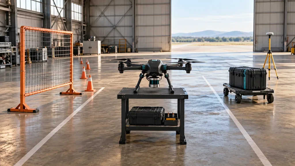
Start with a controlled, repeatable scenario. Record the target material and placement, vehicle motion, sensor orientation, host software version, data interface, and the response being evaluated. Then widen the test conditions one variable at a time. The related dToF LiDAR drone obstacle-avoidance evaluation workflow and the body-frame alignment check are useful internal references for keeping mounting and data-frame questions visible.
MRP-LD1: documented facts for an onboard depth-sensing evaluation
The Featured product for this article is the MRP-LD1 Drone LiDAR Sensor. The table below repeats only current exported product facts. Treat the values as an evaluation baseline for the intended scene, not a substitute for system validation.
| Documented field | MRP-LD1 exported value | Evaluation question |
|---|---|---|
| Mass and power | 8 g; 1.2 W; 5 V supply | Does the aircraft installation accommodate the module and power arrangement? |
| Ranging baseline | 0.5–25 m indoors; 0.2–8 m outdoors | Do target distance, angle, ambient light, and motion match the intended evaluation? |
| Field of view | 60° horizontal × 45° vertical | Which forward, downward, or other sector is actually covered after mounting? |
| Depth format | 40 × 30 resolution at 10 fps; depth and point-cloud output | What host-side filtering, timing, and decision logic will consume the output? |
| Interfaces and software support | UART, UVC, UDP; Windows, ARM, Linux, and Android listed | Which interface is the host ready to validate, and how will frames be logged? |
| Listed application groups | UAV obstacle avoidance and altitude hold; robot navigation and obstacle avoidance; AR/VR auxiliary focusing; industrial inspection and security | Which application claim is being tested, and what remains the responsibility of the complete host system? |
MRP-LD1 provides depth images and 3D point-cloud data for host-side evaluation. It is not described as a complete drone obstacle-avoidance system: the host processor, perception logic, planning, flight controller, and validated response remain part of the complete system.
Illustrative case: one aircraft program, two evidence lanes
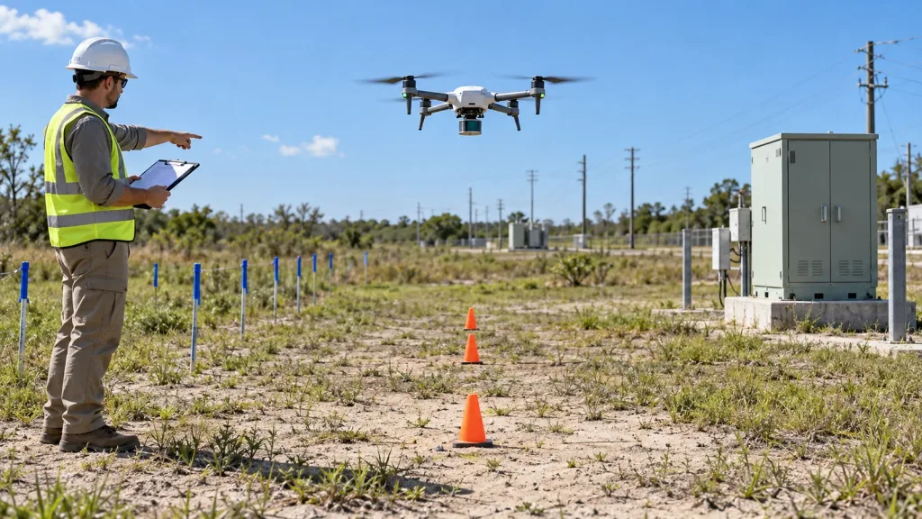
Consider a utility-yard team that initially asks for a LiDAR drone to document assets and also wants closer-proximity awareness around a repeatable inspection route. The project lead separates the request. The mapping lane defines the required post-flight deliverable, target assets, coordinate/data owner, scene conditions, and review sample. The onboard lane mounts a compact depth module, records its observed sector, parses a selected interface on the host, and tests a clearly defined alert or planning input in controlled passes.
The team may later decide that both lanes belong in one program, but it does not treat a survey dataset as evidence of onboard response or a depth-module frame as evidence of mapping deliverables. That separation makes supplier conversations more precise and makes a pilot result easier to audit.
Data and interface handoff: name the owner of every transition
A LiDAR-drone trial commonly fails at the boundaries rather than at the first sensor connection. Write down who owns sensor configuration, physical mount, clock/timestamp handling, frame parsing, coordinate transforms, storage, flight-control boundary, and review of the resulting log. For MRP-LD1, select one documented interface—UART, UVC, or UDP—for the first host test and preserve the raw capture alongside the interpretation. The site article on choosing UART, UVC, or UDP is a practical companion to that handoff.
For a mapping lane, make the same ownership map for collection, positioning data, processing settings, quality review, and final export. A buyer should be able to point to the artifact that proves each handoff, rather than relying on a single attractive point-cloud image.
Common mistakes to avoid
- Calling every LiDAR drone a mapping drone. A compact depth-sensing evaluation and a mapping-payload project have different outputs and evidence.
- Using a maximum range figure as a mission definition. Target material, angle, ambient light, mounting, motion, and data handling still need a scene-matched test.
- Skipping the host-side plan. An onboard depth output does not define perception, planning, or flight-controller behavior.
- Testing only one easy scene. Keep a controlled baseline, then add relevant conditions deliberately.
- Mixing operational compliance with sensor marketing. Check applicable UAS requirements separately from component evaluation.
- Requesting a sample without an acceptance decision. State what the result must demonstrate before the sample arrives.
RFQ and evaluation checklist
- Write the primary output in one sentence: map deliverable, onboard depth input, or two-track program.
- Describe terrain, vegetation, structures, target surfaces, distance band, and expected motion.
- Provide aircraft payload, power, mounting, host, and interface constraints.
- For mapping, request a scene-matched data sample and define the processing/deliverable review.
- For onboard sensing, define the observed sector, selected interface, host data path, and response boundary.
- State which evidence is required: raw logs, processed data, mounting record, scenario protocol, and pass/fail criteria.
- For MRP-LD1 evaluation, share target platform, application, working distance, indoor or outdoor scene, host system, preferred interface, sample quantity, and expected project timing.
- Keep mapping and onboard-sensing acceptance records separate even when they belong to one aircraft program.
Turn the mission brief into a focused evaluation request
If your program needs a compact onboard depth-sensing evaluation, send Purpleriver the platform, scene, working distance, preferred interface, and the response question you need to test. For a mapping project, include the desired deliverable and processing workflow so the discussion starts with evidence rather than a generic specification list.