Mission-scoping guide for UAS teams
Before you compare sensors, decide what has to be proved.
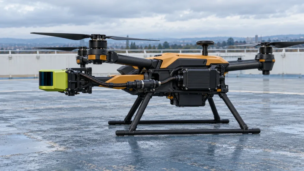
A drone lidar blog should help a project team answer a harder question than “which LiDAR is best?”: what deliverable must survive the pilot? A mapping team may need a documented point-cloud handoff; an inspection team may need repeatable evidence of a defined asset condition; an embedded-UAV team may need a bounded depth-data handoff to its host. Those are different jobs, so they need different test evidence.
That distinction matters when a buyer sees a compact module and a mapping payload in the same search results. Do not let a sensor datasheet stand in for a mission definition. Write the deliverable, the acceptance evidence, and the system owner first—then decide whether a LiDAR belongs in the flight trial.
Quick answer
Drone LiDAR is worth scoping when the team can name the output it needs, the conditions under which it will validate that output, and who owns the final data or control decision. For a mapping job, ask for point-cloud and accuracy-validation evidence. For inspection, define the asset, viewpoint, and decision record. For onboard sensing, define the depth-data interface, host logic, flight-controller boundary, and a safe test plan. A compact depth module can support an onboard evaluation; it is not automatically a survey payload or a complete avoidance system.
Drone LiDAR Blog: choose the deliverable before the sensor
The phrase “drone LiDAR” covers at least three distinct project conversations. Keeping them separate prevents a pilot from producing impressive screenshots but no decision-ready evidence.
- Mapping: the customer needs a point-cloud or elevation deliverable with stated quality expectations, reference information, and validation evidence. The U.S. Geological Survey’s lidar processing guidance is a useful reminder that a data product is more than collected points: its workflow includes validation and reporting of positional accuracy. See the USGS lidar data-processing and handling requirements.
- Inspection: the customer needs a decision about an asset. Define the object, flight geometry, image or point-cloud evidence, reviewer, and pass/fail language before choosing the sensor.
- Onboard sensing: the vehicle needs distance or depth data passed to a host process. The deliverable is an interface-and-behavior evidence pack, not a mapping dataset and not a promise that the aircraft will avoid every obstacle.
For mapping, write the requested density, accuracy convention, land-cover or target conditions, file format, coordinate reference, and validation report into the pilot brief. The USGS quality-level reference shows why density and vertical accuracy are separate requirements; one should not be used as a substitute for the other. This is a planning reference, not a claim that a particular UAV system meets a USGS quality level.
Mission decision chart: what should the pilot prove?
| Mission question | Useful pilot output | Acceptance evidence to name | Do not assume |
|---|---|---|---|
| Can we produce a usable terrain or asset model? | Documented point-cloud or elevation deliverable | Coordinate reference, density/accuracy expectation, check method, processing and handoff record | That any LiDAR payload is survey-ready for the requested deliverable |
| Can the team inspect this specific asset? | Repeatable evidence linked to the asset and review decision | Target list, flight geometry, capture conditions, reviewer and exception handling | That a generic 3D view is sufficient for a maintenance or safety decision |
| Can onboard depth data inform a host workflow? | Timestamped depth/point-cloud sample plus host-side logs | Interface, coordinate convention, update behavior, host consumer, test boundary and fallback behavior | That a depth sensor alone is a complete avoidance or flight-control system |
Use the mission question to route the next conversation
If the deliverable is a geospatial product, continue with our LiDAR for UAV accuracy, payload, and deliverables guide. It helps a buyer turn a vague accuracy request into a pilot brief. If the deliverable is an onboard perception handoff, use the dToF LiDAR drone obstacle-avoidance evaluation workflow as the next planning layer.
Commercial flight operations carry their own obligations. A U.S. team should confirm that its intended operation fits the applicable rule set; the FAA’s commercial-operator guidance is the appropriate starting point for Part 107 questions. Sensor planning does not replace an operational or safety review.
Application case: one utility pilot, two evidence lanes
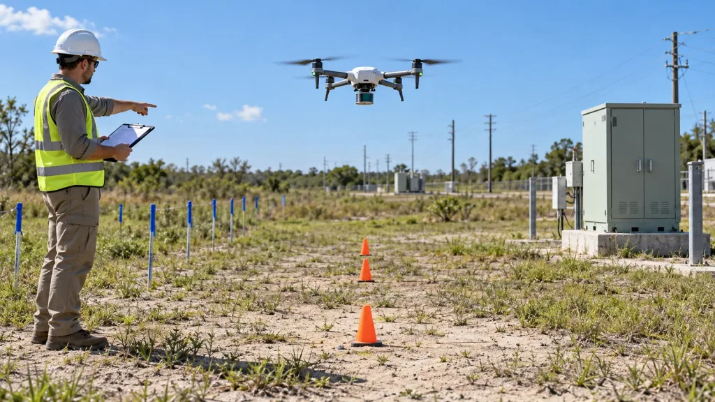
Imagine a utility contractor asked to evaluate LiDAR on a small UAV. The request arrives as “we need a 3D scan and better obstacle awareness.” That sentence contains two independent pilots.
- Inspection/mapping lane: the team names the structures to review, the coordinate reference and output format, the expected review artifact, and the person who will judge whether the data answers the asset question. It keeps any accuracy target tied to a documented validation method.
- Onboard-sensing lane: the team mounts a compact depth sensor only for a controlled data-handoff evaluation. It records the sensor output, the receiving host process, frame or coordinate assumptions, and what the flight system does when data are unavailable or rejected.
The two lanes may share a flight area, but they must not share a vague acceptance statement. The first lane produces a data-deliverable record. The second produces integration evidence. For a focused asset workflow, see the related drone LiDAR utility-inspection evaluation checklist.
Where the MRP-LD1 compact module fits—and where it does not
Purpleriver’s Featured MRP-LD1 Drone LiDAR Sensor is documented for embedded depth-perception evaluation. The table below repeats only the supplied product fields. Use it to decide whether an onboard depth-data trial is worth planning; do not read it as a promise of mapping performance or autonomous flight behavior.
| Documented parameter | MRP-LD1 value | Planning implication |
|---|---|---|
| Weight and power | 8 g; 1.2 W | Record payload, power, mounting, and thermal checks in the integration plan. |
| Documented ranging baseline | 0.5–25 m indoors; 0.2–8 m outdoors | Build tests around the intended target, ambient light, angle, mounting, and motion; validate the intended scene. |
| Field of view and frame output | 60° horizontal × 45° vertical; 40 × 30; 10 fps | Check coverage, blind sectors, timing, and the host’s data-use assumptions rather than extrapolating beyond the documented view. |
| Data and interfaces | Depth images and 3D point-cloud data; UART, UVC, UDP | Choose one interface and define the parsing, timestamps, coordinate convention, logs, and fault handling before flight. |
| Software support | Windows, ARM, Linux, Android | Name the actual host platform and capture tool in the pilot record. |
The module supplies depth images and 3D point-cloud data. The host processor, perception logic, planning, flight controller, and validated response remain parts of the complete system. That boundary is the reason an onboard proof should be designed as a data-contract test, not an “avoidance demo.”
Data and integration: make the handoff reviewable
A compact sensor trial becomes useful when another engineer can reproduce the handoff. Put these items in the test record:
- sensor interface selected for the trial—UART, UVC, or UDP—and the host platform;
- the exact output consumed: depth image, point cloud, or both;
- mounting orientation and the coordinate/frame convention used by the host;
- how timestamps, dropped frames, invalid values, and logging are handled;
- the boundary between sensor evidence, companion-computer logic, and flight-controller authority; and
- a safe fallback and test-stop condition that does not depend on a single unverified perception input.
For a deeper handoff worksheet, use our LiDAR sensor data contract and flight-controller integration guide. It is more valuable to record one unambiguous interface trace than to claim a system is integrated because a visualization appeared on a screen.
Common mistakes that make a drone LiDAR pilot hard to evaluate
- Starting with sensor taxonomy. A list of wavelengths, ranges, or interfaces does not identify the mission’s decision owner.
- Calling all 3D data “mapping.” A depth frame, an inspection capture, and a controlled point-cloud deliverable require different evidence.
- Using a product specification as a field result. Keep the documented specification separate from the conditions and measurements of your own test.
- Skipping the data contract. If the host cannot explain which bytes, frames, timestamps, and failures it handles, the integration result is not reviewable.
- Equating detection with avoidance. A sensor data stream does not replace host perception, planning, flight control, and validation.
- Leaving the regulatory check until after the sensor work. Confirm operational requirements as part of the mission scope.
RFQ and pilot checklist
- What decision will the customer make from the deliverable?
- Is the mission mapping, inspection, onboard sensing, or a deliberately separated combination?
- What output format, coordinate reference, or host interface is required?
- What target, working-distance band, environment, mounting position, and motion will be represented?
- Who owns ground/reference checks, data review, host software, and flight-control behavior?
- What metrics or review rules make the pilot pass, fail, or require another test?
- Which logs, source data, and configuration details must be retained for handoff?
- What safety and operating review applies before any flight test?
Turn the question into an evaluation brief
Send Purpleriver your platform, mission type, indoor or outdoor scene, target working distance, host system, preferred interface, sample quantity, and project timing. We can help you identify the product documents, SDK resources, sample data, or evaluation sample information relevant to a documented MRP-LD1 depth-data trial.