Perception architecture evaluation
Omnidirectional Binocular Vision System: A Coverage-and-Calibration Evidence Plan
When a warehouse-robot team asks for an omnidirectional binocular vision system, the phrase can hide four different requirements: perimeter coverage, calibrated stereo geometry, usable depth output, and a host that can process it at the required rate. Treating those as one checkbox is how a visually impressive demo becomes a difficult pilot. This guide turns the phrase into evidence a technical buyer can request, inspect, and compare.
Quick answer
An omnidirectional binocular vision system should be evaluated as a coverage-and-data contract, not simply as “two wide-angle cameras.” Define each protected sector and overlap, retain the camera calibration and stereo rectification evidence, test depth confidence on representative targets, and measure host processing under the real route. If the architecture also needs an active dToF input, assess that module as a separate sensing path with its own field of view, interfaces, and test conditions.
What an Omnidirectional Binocular Vision System Must Prove
“Omnidirectional” is a coverage requirement. It should name the sectors around the platform, the elevation band that matters, fixed obstructions, and the allowed gaps between camera views. “Binocular” is a geometry-and-processing requirement: two image streams need a stable relative pose, camera parameters, rectification, and a correspondence method before a depth map can be evaluated. OpenCV’s current calibration documentation describes the intrinsic parameters, lens distortion, stereo-head relative pose, and rectification steps behind that workflow; its camera-calibration and 3D-reconstruction reference is a useful baseline for the evidence request.
Neither term means “active ranging.” A dToF module measures its own depth output; a binocular system derives depth from paired images. They can be complementary in a perception stack, but a supplier should not be allowed to relabel one as the other. That distinction keeps acceptance testing honest and makes it easier to assign each output to the right frame-and-point-cloud handoff.
Choose the Evidence, Not the Marketing Label
| Decision question | Evidence to request | Acceptance check |
|---|---|---|
| Which sectors must the robot observe? | A sector map with camera positions, intended overlap, blind-zone assumptions, and mounting height. | Walk the route with target positions at aisle entries, turns, and dock edges; record every unexplained gap. |
| Can the camera pair produce defensible stereo depth? | Intrinsics, distortion model, relative stereo pose, rectification output, and the calibration target/procedure version. | Repeat the calibration check after mounting and after a representative vibration or thermal condition. |
| Can the host process the real workload? | Input resolution, frame rate, processing stages, latency measurement point, and compute/power conditions. | Run the actual route and traffic pattern, not an isolated desktop image sequence. |
| Is an active depth module also needed? | A separate field-of-view, range-condition, output, and interface statement for that module. | Test it in the same target locations without claiming it is a binocular camera. |
| Can downstream software trust the output? | Coordinate-frame convention, timestamps, validity/confidence handling, and example records. | Trace a sampled result from sensor output to the navigation or safety-review log. |
Build a Stereo-Calibration Evidence Pack Before the Pilot
Start with a written reference frame. For each camera, preserve the resolution used during calibration, its intrinsic matrix, lens-distortion coefficients, and the calibration-pattern record. For the pair, preserve the relative rotation and translation, plus the rectification version used to create the matched image views. A calibration result that looks acceptable near the image center can still be unsuitable at the edge of a wide-angle view; that is why the artifact and the route-level check both matter.
- Freeze the intended mount. Calibrate with the production-like bracket, lens covers, and camera orientation—not a temporary bench arrangement.
- Record the transform. Give the two camera heads unambiguous frame names and preserve the transform that the stereo pipeline used.
- Rectify before judging correspondence. Stereo matching assumes the images have been geometrically prepared for that step. OpenCV’s stereo depth-map tutorial shows rectification and stereo matching as distinct stages.
- Use representative targets. Include the aisle materials, labels, pallet edges, wrap, and lighting transitions that the robot will actually see. Log where a result is invalid or uncertain instead of silently filling it in.
- Measure the whole pipeline. The relevant result is capture-to-consumer timing under the intended workload. Texas Instruments identifies stereo-depth estimation as a compute-intensive task for robots and drones in its edge-AI systems paper; plan the host test accordingly.
Where a Compact dToF Module Fits—and Where It Does Not
An active dToF module can be assessed as a separate depth input in the overlap area that matters to the robot. It does not turn an architecture into an omnidirectional binocular vision system. Keep the coverage map, calibration evidence, output contract, and pilot criteria separate; then decide whether the two sensing paths meet different parts of the requirement.
The current Featured product is the MRP-LD1 Drone LiDAR Sensor. The table below reproduces only facts supplied for that Featured product; it is not a performance promise for any particular robot installation.
| Featured-product field | MRP-LD1 stated value | Evaluation implication |
|---|---|---|
| Ranging principle | SPAD dToF; solid-state architecture | Evaluate it as an active depth module, not as a binocular camera. |
| Stated ranging capability | 0.5–25 m indoors; 0.2–8 m outdoors | Define target, lighting, and distance conditions before comparing results. |
| Field of view and output | 60° (H) × 45° (V); 40 × 30; 10 fps | Place it on the coverage map and verify the required sector rather than assuming full perimeter coverage. |
| Interfaces | UART, UVC, UDP | Confirm the chosen host path, framing, and application data contract. |
| Host support | Windows, ARM, Linux, Android | Use the target host and OS in the integration test. |
| Electrical and mass | 5 V; 1.2 W; 8 g | Include it in the platform’s measured power and mounting plan. |
| Stated accuracy bands | 0.2–1 m ≤ ±3 cm; 1–5 m ≤ ±5 cm; 5–8 m ≤ ±10 cm; 8–15 m ≤ ±20 cm | Write the specific target and environment into the test record; actual results can be affected by reflectivity, ambient light, and use conditions. |
For a host-side review, pair this section with the site’s SDK validation guide and use the product’s documented interface rather than assuming a common payload format.
Application Case: A Cross-Aisle Robot That Must See the Turn Before It Takes It
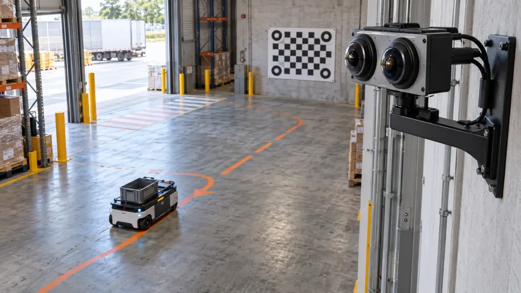
Example evaluation pattern, not a customer result: a mobile robot moves from a storage aisle into a cross-aisle where wrapped pallets, racking uprights, and an open loading-bay entrance create changing image content. The team places a binocular camera pair high on the robot, records its camera-to-robot transform, and maps the camera overlap against the turn geometry. A calibration fiducial board at the far wall makes a repeat check possible without turning the route into a laboratory.
For the forward approach area, the team separately maps a compact dToF module’s stated 60° × 45° field of view. The acceptance sheet does not declare one sensor “better.” It asks: which targets are covered by the camera pair; where is a usable stereo result expected; which measurement is sent to the navigation stack; and what occurs when an output is invalid? That produces a testable handoff instead of an architecture claim.
Teams evaluating a depth workflow in a more constrained workcell can also adapt the coverage and data-handoff portions of this 3D depth sensor pilot plan. The route, targets, and acceptance limits still need to be specific to the robot deployment.
Data and Integration Handoff
Make the interface review a deliverable, not an afterthought. The binocular pipeline should state image timing, calibration version, frame identifiers, stereo-processing output, and how invalid or low-confidence results are represented. The dToF path should separately state which MRP-LD1 interface is used—UART, UVC, or UDP—along with the host, parser/version, timing handling, and coordinate transform. A single “depth topic” without provenance makes later diagnosis needlessly difficult.
During the pilot, save a small replay bundle: sensor configuration, calibration artifact, route map, raw or approved diagnostic records, processed output, and navigation-side outcome. This lets the team reproduce an exception when lighting, target finish, or mounting changes. For placement evidence, the mounting-height and pitch test guide is a useful complementary checklist.
Common Mistakes
- Calling a wide-angle camera pair “omnidirectional” without a sector map. Name the coverage gaps, overlap, and occlusions.
- Testing stereo depth before the production-like mount is stable. A bench calibration does not replace a mounted-system check.
- Judging a depth image without preserving the calibration version. A future team cannot reproduce a result from a screenshot alone.
- Mixing active dToF output and stereo output under one unnamed data stream. Keep source, confidence/validity, transform, and timing traceable.
- Using only a clean target in a quiet aisle. Include the actual materials and route transitions that motivated the project.
- Concluding system performance from a component specification. Integrator testing is still required for the robot, environment, and control logic.
RFQ and Evaluation Checklist
- Provide a perimeter-sector map with required elevation band, overlap, occlusions, and acceptance target locations.
- Request stereo intrinsics, distortion model, relative pose, rectification version, and calibration procedure.
- Specify the intended robot mount, vibration/thermal conditions, and a repeat-calibration criterion.
- Name the route, representative surfaces, lighting transitions, and unacceptable blind zones.
- Define capture-to-consumer timing, host hardware, resolution, frame rate, and workload for the binocular pipeline.
- For MRP-LD1, select UART, UVC, or UDP and request the matching integration documentation and diagnostic path.
- Record coordinate frames, timestamps, validity/confidence handling, and the consumer of each output.
- Require a pilot report that separates stereo evidence from active dToF evidence and lists unresolved limitations.
Turn the requirement into an evaluation request
If your project needs a compact active depth input alongside a camera-based coverage design, start with the MRP-LD1’s documented field of view, interfaces, host support, and stated operating conditions. Share the sector map, host platform, and data-handoff requirements so the evaluation can be scoped to the actual integration—not a generic demo.