LiDAR Selection & Buying
940nm VCSEL Solid State LiDAR: A Buyer’s 7-Test Evidence Plan
A 940nm VCSEL solid state LiDAR label can help narrow a component search, but it is not a deployment result. Before a sample is accepted or a pilot is approved, a buyer needs evidence that connects the documented module, the real target and light conditions, the host data path, and the application’s own acceptance criteria. This guide turns that task into seven reviewable tests.
Quick answer: evaluate the evidence chain, not the label
Start by separating four things: what the supplier documents about the component, what your optical scene demands, what the host actually records, and what the complete application must do. Record each test condition, preserve the raw result, and decide in advance what observation will move the evaluation forward. A published 940 nm VCSEL, solid-state architecture, or ambient-light figure is useful input; it is not proof of performance for every target, mount, motion profile, or safety decision.
For a compact module, the practical sequence is simple: confirm the published facts, define the target and distance band, challenge the intended light condition, capture the chosen interface, compare repeatable runs, document limits, and retain the laser-product documentation that belongs with the integration review.
1. What the label does—and does not—tell you
In this search phrase, 940 nm identifies the stated VCSEL wavelength, VCSEL identifies the listed laser source, and solid state tells a buyer which product family is being considered. Those terms are useful for requirements matching. They do not, on their own, establish usable working range, target response, resistance to a particular illumination setup, host compatibility, or a system-level safety conclusion.
This distinction matters especially for SPAD dToF evaluations. A current primary study of SPAD-based dToF ranging examines dead-time and pile-up effects and identifies optical photon flux, pulse width, and time quantization as precision-relevant variables. Its useful buyer lesson is not a copied specification: it is to keep optical conditions and repeatability visible in the evidence record. See the 2025 SPAD dToF precision study for the underlying research.
Likewise, a wavelength is not a substitute for laser-product documentation. The supplied MRP-LD1 record includes its Class 1 FDA-recognized eye-safe wording; retain that supplied product documentation with the module record and have the responsible team assess the actual integration. The FDA’s laser-product guidance distinguishes hazard classes and explains why classification and risk management belong to the product discussion.
2. Use this decision table before approving a sample
| Buyer question | What a datasheet field can support | Evidence still needed | Responsible next step |
|---|---|---|---|
| Is this the intended component family? | Match the 940 nm VCSEL and solid-state dToF description to the architecture you are investigating. | Target type, range band, field coverage, mount, and the application’s own acceptance condition. | Write a one-page test objective before requesting a sample. |
| Will it work in our light and scene? | Use published ambient-light and range baselines to plan a starting condition. | Representative target material, angle, background, illumination, and repeatability results. | Run controlled indoor and intended-environment captures; record the conditions. |
| Can our host use the output? | Identify documented interfaces and supported host platforms. | The selected transport, framing, parser, storage, timestamps, and application-side review. | Capture raw outputs through the intended host before promising a pilot. |
| Is it safe for the project? | Keep the supplied classification wording with the product record. | Installation-specific controls, labels, operating context, and the responsible team’s review. | Request and retain the relevant product documentation; do not infer classification from wavelength. |
| Should we release a purchase or pilot? | Use the component facts to establish a testable shortlist. | Passed evidence for the exact use case plus known limitations and open risks. | Approve only the staged evaluation decision—not an unsupported universal claim. |
3. Run the seven-test evidence plan
Test 1 — freeze the component record
Make a single source-bounded record of the module’s published parameters, part identity, firmware or sample identity if supplied, and the date you received the information. This prevents a test observation from being attached later to a different configuration. Link the record to the MRP-LD1 Drone LiDAR Sensor page rather than restating unlisted claims in an RFQ.
Test 2 — define one target-response question
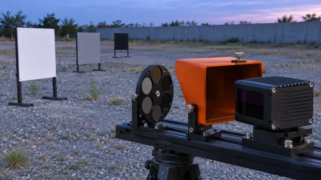
Choose a scene that represents a decision you actually need to make: for example, whether a matte panel, a dark edge, and a lightly reflective return remain distinguishable at the planned distance band. Name the panel materials, their positions, the observation angle, the sensor mount, and the pass observation before capture. A clear question is more useful than a broad request to “test range.”
Test 3 — record optical conditions deliberately
Run a baseline in a controlled condition, then repeat under the intended light situation or a defensible approximation. Record the source of illumination, direction of light, target orientation, background, and any shielding. Do not turn a single successful frame into an ambient-light guarantee. This test exists to show which condition was actually evaluated and whether the observation changed.
Test 4 — step through the geometry
Move targets through a documented set of distances and angles within the intended evaluation envelope. Keep a simple position ledger and a photo or drawing of the fixture. If a target is weak, intermittent, or outside the desired field, keep that result. The point is to define the boundary of the experiment, not to curate only favorable scenes.
Test 5 — capture raw host evidence
Select the intended interface, save the unmodified source output, note the host platform, and attach a run identifier. A screenshot alone is not enough: preserve the file or stream capture that another engineer can reopen. The existing compact dToF evaluation workflow is a useful companion for making this handoff traceable.
Test 6 — repeat and compare a limit condition
Repeat a favorable capture and one meaningful limit condition using the same documented setup. Compare the raw observations rather than averaging them into a claim. Note what remains stable, what changes, and what you cannot explain yet. This is where component facts become project evidence.
Test 7 — close the documentation loop
Archive the source record, fixture notes, raw captures, product documentation, and the acceptance decision together. If a sample moves forward, record the unanswered risks as explicit next tests. If it does not, record why without rewriting the product facts. This gives procurement and engineering the same audit trail.
| Evidence artifact | Minimum contents | Why it matters |
|---|---|---|
| Test card | Run ID, module record, target set, distance/angle plan, and pass observation. | Makes the question reviewable before data is collected. |
| Condition log | Light source, target material/orientation, mount, background, host, interface, and date. | Stops a scene-specific result being mistaken for a general capability. |
| Raw capture bundle | Unmodified output plus parser/tool version and timestamp convention. | Lets another engineer reproduce the host-side observation. |
| Decision note | Observed fit, limit, open question, and next action. | Keeps a sample decision separate from an unsupported deployment promise. |
4. Keep the documented MRP-LD1 facts source-bounded
The featured product is a compact evaluation option, not a promise for an untested installation. The table below reproduces only relevant facts supplied for the MRP-LD1. Treat every application result as something your own evidence plan must establish.
| Published MRP-LD1 parameter | Supplied value | How to use it in this plan |
|---|---|---|
| Architecture and source | Solid-state SPAD dToF; 940 nm VCSEL | Use it to define the component family; do not use it as a result for a specific scene. |
| Published range baselines | 0.5–25 m indoor; 0.2–8 m outdoor | Plan initial fixture positions, then record actual target and condition results. |
| Field of view | 60° horizontal × 45° vertical | Draw the intended coverage and verify installation occlusions. |
| Depth output | 40 × 30 resolution at 10 fps | Set a realistic capture and review plan for the intended host workflow. |
| Interfaces and software | UART, UVC, UDP; Windows, ARM, Linux, Android | Choose one actual host path and preserve its raw output. |
| Ambient-light specification | 80 klux ambient-light resistance | Use as a documented planning input, not a substitute for your light-condition test. |
| Integration envelope | 5 V, 1.2 W, 8 g | Check the host budget and mount; validate the whole assembly separately. |
| Supplied safety wording | Class 1 FDA-recognized eye safe | Retain the supplied documentation and do not reduce a safety review to wavelength alone. |
For documents that should travel with a sample, use the documentation resources. If a pilot also needs representative files for a host-side review, ask for the appropriate materials through the sample-dataset resources; do not imply that a supplied sample dataset proves your own scene.
5. Prove the data path and host handoff
Component evaluation can fail even when the optical observation looks promising. State which of the documented UART, UVC, or UDP interfaces you will use, the host operating system, the capture utility or parser version, file format, timestamp source, and the person who can reopen the raw material. These are acceptance questions, not minor implementation details.
At the review table, show four items together: the run card, the raw capture, one faithful rendered view, and the decision note. Keep downstream perception, planning, and application response visibly outside the component claim unless they were evaluated as their own system test. Before ordering a sample, compare this list with the existing LiDAR module evaluation-sample checklist.
6. Illustrative application: a loading-dock approach check
Consider an engineering team assessing a compact module for a slow mobile inspection cart that approaches an exterior loading dock. This is an illustrative evaluation scenario, not a measured customer result. The team places white, gray, and black matte panels at its expected observation distances, first under a shaded canopy and then near the dock opening. It fixes the module position, records the light direction and panel angles, captures raw output through the selected host interface, and repeats the least favorable panel position.
The useful outcome is not “the sensor works outdoors.” It is a decision note such as: “Under the recorded test setup, the selected panels were or were not distinguishable in the saved captures; the next test must examine the remaining target and mounting questions.” That note has a defined scope and is far more actionable for a pilot decision.
7. Common mistakes when buying by wavelength or architecture
- Equating 940 nm with a guaranteed outcome: wavelength is one component fact, not a complete scene-performance result.
- Copying published range into an acceptance sheet: use the published baseline to design a test, then preserve the observations from your actual target, light, angle, and mount.
- Calling a rendered image raw evidence: retain the original output and the host/tool context behind any view used in a decision.
- Testing only a cooperative target: include the relevant surface and geometry limits early, and report the condition honestly.
- Assuming interface names prove integration: a UART, UVC, or UDP listing still needs a recorded host capture and review path.
- Treating a safety phrase as a system sign-off: preserve the supplied classification documentation and assign the integration review to the responsible team.
- Approving a pilot without a failure record: a known limitation is useful evidence; an undocumented one becomes a surprise.
8. RFQ and sample-evaluation checklist
Before requesting an evaluation sample or a project-specific response, send the information that allows a supplier and your engineering team to discuss the same test:
- The intended platform and application, including whether the module is fixed, mobile, robotic, or airborne.
- The target types, distance band, target angles, background, expected light conditions, and the one observation that would count as useful evidence.
- Mounting space, 5 V power budget, weight constraint, field-of-view direction, and any likely occlusions.
- The selected UART, UVC, or UDP path; host operating system; desired raw output; and the person responsible for replaying a capture.
- Required documents, sample identity/traceability, and the product classification information your organization needs to retain.
- A staged decision: bench evidence first, representative-environment evidence next, then a separately scoped system pilot if the earlier evidence supports it.
Turn the 940 nm label into a reviewable evaluation
Bring your target, light, mounting, host-interface, and evidence requirements to the discussion. The right next step is a bounded sample evaluation with a result another engineer can inspect—not a promise based on a keyword alone.
Discuss an MRP-LD1 evaluation or documentation request with the project context and test card.