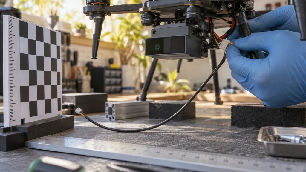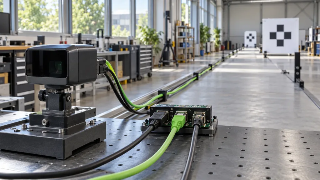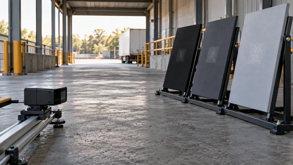
A robot navigation sensor is not ready for a pilot merely because data appears on a host computer. Before a mobile-robot team treats a depth feed as useful input, it must document what the sensor measures, which coordinate frame owns the observation, what the receiving component can interpret, and what happens when data is missing or unsuitable. This guide turns those questions into a practical handoff checklist for a compact 3D depth source such as the MRP-LD1 Drone LiDAR Sensor.
Quick answer
Evaluate a robot navigation sensor as an input contract, not a range number alone. For the first pilot, record the physical mounting frame, transform path to the robot base, expected fields and timestamps, invalid-data behavior, and evidence that proves the handoff. MRP-LD1 is a compact SPAD dToF module with listed UART, UVC, and UDP interfaces; suitability for a particular robot still depends on mounting, data conversion, and supervised validation.
Robot navigation sensor: choose the handoff before the pilot
A navigation system cannot make a dependable decision from an unlabeled depth grid or point cloud. It needs enough context to relate every observation to the robot and its environment. Start the engineering review with the sensor mounting, transport interface, source-data interpretation, coordinate-frame ownership, and test evidence.
For teams using ROS conventions, ROS REP 105 supplies shared definitions. It distinguishes the rigid robot base_link frame from the locally continuous but drifting odom frame and the globally useful but potentially discontinuous map frame. A project may use different software, but it still needs an explicit owner for every transform before a sensor observation reaches a navigation component.
This changes a buying conversation for the better. Instead of asking only for sensor range, ask whether the team can preserve source time, define mounting orientation, expose invalid observations, and replay a supervised evaluation. Those are useful questions for both an integration engineer and a technical buyer.
Frame-and-data decision chart
| Decision | Record before pilot | Accept when | Escalate when |
|---|---|---|---|
| Physical sensor ownership | Mounting location, orientation, bracket revision, sensor-frame name | The frame is tied to robot base by a documented repeatable transform | The bracket moves, orientation is guessed, or names change between tools |
| Observation identity | Depth, point data, or converted representation; source time and units | A recorded sample is decoded with origin and time intact | A display works but field, unit, or timestamp meaning is unknown |
| Navigation-frame path | Relation among sensor, robot base, local odometry, and map frames | Every relation has an owner and documented purpose | Two components publish competing relationships |
| Invalid-data behavior | Treatment of missing, out-of-range, low-confidence, or malformed input | A supervised route records the chosen behavior | Missing data is silently treated as clear space |
| Pilot evidence | Route, representative targets, logs, reviewer, and rollback condition | The team can replay what the run proves and does not prove | The decision rests on an unlogged demonstration |
The chart separates a module capability from a navigation outcome. A compact depth source can be appropriate evaluation input, while the complete robot still needs its own control design, safety case, and application-specific validation.
MRP-LD1 facts to put in the integration record
The MRP-LD1 Drone LiDAR Sensor is this workflow’s available Featured product. Use these exported facts as a factual starting point, then request the protocol and integration material required for your host. Do not convert a module parameter into a promise about a robot’s stopping distance, map quality, or autonomous behavior.
| Exported field | MRP-LD1 value | Question for the handoff |
|---|---|---|
| Ranging / scanning principle | dToF / SPAD | Which source representation will the host preserve? |
| Output | 40 × 30 | Which rows, fields, and units will the receiver expect? |
| Frame rate | 10 fps | How will source time be captured and logged? |
| Field of view | 60° (H) × 45° (V) | What part of the operating scene is covered after mounting? |
| Listed ranging capability | 0.5–25 m indoors; 0.2–8 m outdoors | Which representative distances belong in the route? |
| Interfaces | UART, UVC, UDP | Which connection and conversion path will be versioned? |
| Power / mass | 5 V / 1.2 W / 8 g | Can the mount, cable route, and power budget be reviewed together? |
| Software support | Windows, ARM, Linux, Android | Which host will own capture and reproducible parsing? |
For adjacent setup context, compare UART, UVC, and UDP integration paths and the dToF LiDAR Raspberry Pi and Linux guide. Neither replaces the project-specific review below.
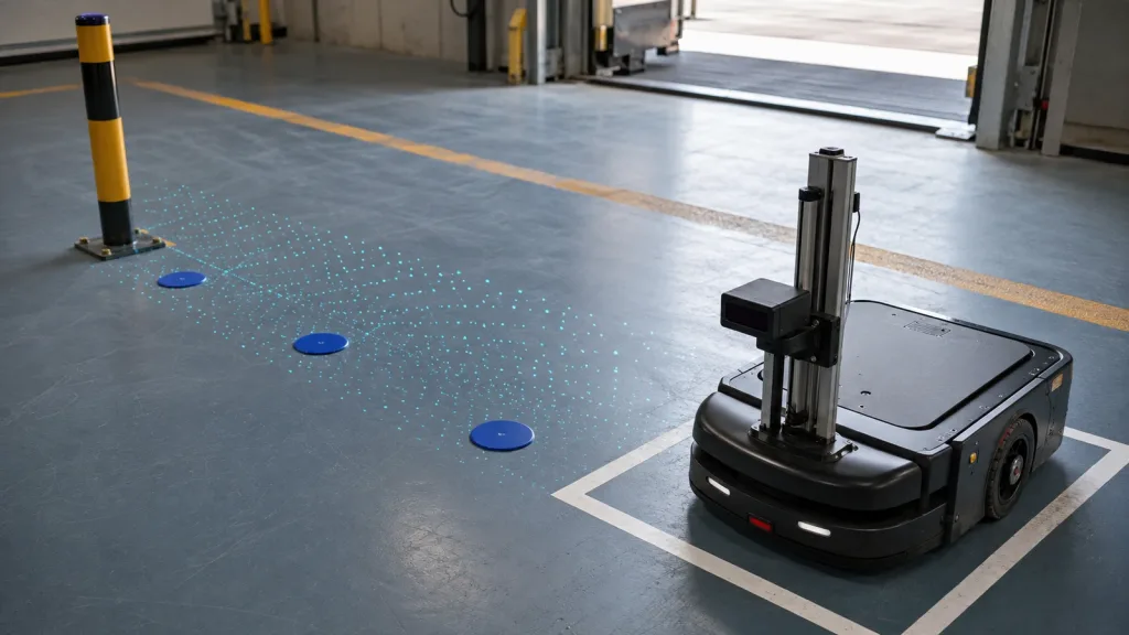
Illustrative case: supervised AMR loading-dock handoff
Imagine a compact AMR approaching a marked loading-dock staging square during a supervised pilot. The team mounts the sensor on the front mast, records bracket orientation, and assigns a stable sensor-frame name. The route is not a claim that the robot is autonomous. It establishes whether the team can capture, label, transform, and review source observations.
One engineer owns the sensor-to-robot transform, one owns host-side capture configuration, and one reviewer defines the route and log location. A fixed reference post beside the staging square gives the team a repeatable scene. After a slow approach, the reviewers check whether the recorded data relates to the intended robot frame and whether every expected observation has usable time and interpretation evidence. A failed handoff is an integration finding, not a reason to silently relabel data.
For application context, use Purpleriver’s robotics 3D mapping solution page and the mounting-height and pitch floor-intercept guide. The case here remains a frame-and-data review, not a performance guarantee.
Make the frame and point data interpretable
Assign a transform owner
Write down who creates and validates the sensor-to-base relationship. A transform expresses how the observation is positioned and oriented relative to the robot; it is not a label added afterward. A bracket change is a change to the integration record. Also record whether local odometry and global map correction are owned by different components, so a reviewer can understand why a local path may be smooth while a global pose can update.
Define the receiving-side point contract
The current ROS PointCloud2 definition describes N-dimensional point collections whose layout is described by fields, together with acquisition time and coordinate-frame ID. It also identifies dimensions, point and row steps, binary data, and whether the cloud is dense. Even with different middleware, record equivalent facts instead of treating a point-cloud label as enough.
For an MRP-LD1 evaluation, document the source protocol separately, then create a reproducible parser or conversion only after the team agrees on field meaning, units, source time, frame ID, and invalid-data treatment. Do not imply a native ROS message or navigation plug-in unless it is supplied and verified for the particular project.
Separate display from usable input
A visualization can help debugging, but it is not accepted navigation input. A viewer may render points while their timing, frame, scale, or invalid values remain misunderstood. Use the depth-map versus point-cloud explainer for terminology and the point-cloud dataset evaluation guide for sample-review context.
Common mistakes that delay a pilot
- Calling a display a handoff. Rendered points do not establish timestamp, units, frame, or validity rules.
- Mounting first and naming the frame later. Treat orientation and the transform as controlled integration inputs.
- Mixing local and global pose expectations. Document which component owns each reference.
- Using product range as route acceptance. The listed range is a module fact; the route still needs representative geometry and environment.
- Concealing invalid observations. Decide how the receiver identifies unsuitable input before the route.
- Changing a parser without a record. Version host configuration and conversion so later logs remain interpretable.
Keep the LiDAR integration diagnosis guide with the pilot packet for adjacent fault-isolation context.
RFQ and evaluation checklist
- State robot type, mounting location, and the scene area to observe.
- Confirm interface—UART, UVC, or UDP—and evaluation host.
- Request the relevant protocol, data-format, SDK, and version information.
- Define sensor-frame name, transform owner, and mounting-change review.
- Record receiver expectations for fields, units, source time, frame, and invalid values.
- Choose a supervised route with representative geometry and a named reviewer.
- Set a log location, parser/configuration version, and pass/review record before testing.
- Keep project requirements separate from the verified MRP-LD1 exported facts.
Plan the handoff before requesting a sample
Share your robot type, preferred interface, host platform, mounting concept, and observations to evaluate. Purpleriver can help start a focused MRP-LD1 integration discussion using available product documentation and your project requirements.