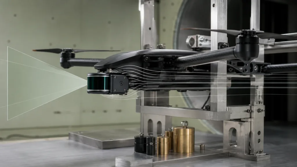
Quick answer: To choose a LiDAR sensor for drone integration, use two layers: hard gates for flight safety and compatibility, then a weighted score for desirable features. Hard gates should cover installed mass, voltage/power, usable range in the real target/light matrix, mounted field of view, end-to-end timing, interface support, data semantics, environmental limits, and supplier evidence. A high score cannot compensate for a failed gate.
Start with a LiDAR sensor for drone requirement sheet
Begin with aircraft and mission values, not a supplier catalog: maximum approved relative speed, required look directions, smallest target of interest, target finishes, operating illumination, precipitation/dust policy, minimum separation, host computer, flight controller, available ports, voltage rail, payload budget, and expected log format. Mark each value as required, preferred, or unknown.
Define the role precisely. A downward sensor for altitude hold has a different geometry and terrain problem from a forward array used for obstacle sectors. A mapping payload has accuracy, synchronization, pose, calibration, storage, and georeferencing requirements that differ from near-field collision prevention. PX4’s distance-sensor guide lists uses including terrain following, landing, and collision prevention; those uses should not be collapsed into one vague “drone LiDAR” requirement.
If the mission is obstacle sensing, connect this requirement sheet to the site’s drone avoidance architecture overview. If the mission is payload selection more broadly, use the UAV LiDAR accuracy and deliverables guide to distinguish perception output from mapping deliverables.
Turn field of view into a mounted coverage envelope
FoV is an angle, not an obstacle width. For a centered idealized cone, horizontal span at distance d is approximately 2d × tan(horizontal FoV / 2). A 60° horizontal FoV therefore spans about 1.15 times distance: roughly 2.3 m wide at 2 m and 5.8 m wide at 5 m. This is geometry, not a claim that every target in that rectangle will be detected.
Repeat the calculation vertically, then overlay aircraft pitch, yawed translation, propeller disks, landing gear, and the sensor’s minimum range. Inspect the corners of the depth array because a rectangular projection, lens behavior, target angle, and invalid pixels can make practical coverage different from a simple cone sketch. Validate with physical targets after the final bracket and optical window are installed.
| Geometry question | Why it changes selection | Evidence |
|---|---|---|
| Where is the sensor origin? | Offsets change the protected envelope and minimum clearance | CAD frame plus measured installation |
| Which body direction does it face? | Flight stacks need correct orientation and transforms | Frame convention and logged transform |
| What blocks the frustum? | Airframe and payload can create repeatable blind zones | Mounted sweep with a small target |
| How does pitch change look-ahead? | Acceleration and braking tilt the coverage volume | Attitude-overlaid test logs |
| What is the minimum usable range? | A near blind zone can remain after a late detection | Close-approach matrix, not a single sample |
Use hard gates before a weighted score
| Criterion | Hard-gate question | Suggested score evidence |
|---|---|---|
| Usable range | Does it meet required range for every critical target/light cell? | Valid-pixel rate, bias, scatter, and dropout by cell |
| Mounted FoV | Are all commanded directions covered or restricted? | Sector map after occlusion survey |
| Timing | Is measured sensor-to-controller latency inside the budget? | Synchronized raw, host, and controller timestamps |
| Payload | Is installed mass and center-of-gravity change acceptable? | Scale measurement of module, mount, cable, regulator, enclosure |
| Electrical | Can the rail handle steady and transient demand? | Power trace during start, stream, and fault recovery |
| Interface | Can the target host receive and validate the data? | Recorded raw stream plus parser/replay test |
| Environment | Does the approved matrix pass? | Light, target, temperature, vibration, window-contamination results |
| Evidence/support | Are specifications and protocol materials controlled? | Datasheet revision, protocol, SDK, sample data, change process |
After all gates pass, assign weights that reflect the program. A small racing platform may weight installed mass and latency heavily; a slow indoor inspection aircraft may weight short-range completeness and integration effort; an outdoor platform may weight bright-scene valid-data behavior. Record weights before reviewing results to reduce after-the-fact bias.
Budget the installed system, not only the module
The installed chain includes mounting hardware, vibration isolation if required, optical protection, cable and connector, regulator, host compute, storage, thermal path, and software. Measure center-of-gravity change and vibration at the sensor, not only total grams. Test the power rail during startup, continuous streaming, cable movement, and host reboot.
Interface names do not guarantee integration. With UART, define electrical level, baud, framing, endianness, CRC, timestamp strategy, and recovery. With UVC, define the selected format, resolution, effective payload, buffering, and frame timestamps. With UDP, define addressing, packetization, loss/reordering handling, and clock alignment. The SDK validation guide and flight-controller data-contract guide cover the software evidence to retain.
When converting output for an autopilot, use the official MAVLink message definitions as the data contract. A single range can populate DISTANCE_SENSOR; an angular obstacle representation may use OBSTACLE_DISTANCE. A 2D depth array still needs documented host logic to transform pixels into body-frame sectors and reject stale or invalid samples.
Example candidate: MRP-LD1 published specifications
The Featured MRP-LD1 provides a concrete candidate for a compact depth-sensing pipeline. The table preserves its published indoor/outdoor distinction and makes no aircraft-level performance claim.
| Verified product field | MRP-LD1 published value | Integration meaning |
|---|---|---|
| Ranging principle | SPAD direct time of flight (dToF) | Produces depth measurements; avoidance decisions remain in the host stack |
| Emitter | 940 nm VCSEL | Include target and sunlight tests at the actual mounting geometry |
| Depth output | 40 × 30 at 10 fps | Treat it as a depth grid, not as a single guaranteed stop signal |
| Field of view | 60° horizontal × 45° vertical | Map the mounted FoV into vehicle sectors and document uncovered directions |
| Published range | Indoor 0.5–25 m; outdoor 0.2–8 m | Keep indoor and outdoor envelopes separate; qualify usable range by target and light |
| Ambient-light resistance | 80 klux | A specification to test under a defined matrix, not permission to skip bright-scene validation |
| Interfaces | UART, UVC, UDP | Select a transport that the host can timestamp, parse, health-check, and replay |
| Power and mass | 5 V, 1.2 W, 8 g | Budget regulator, cable, mount, compute, and protection in addition to the module |
| Software support | Windows, ARM, Linux, Android | Confirm the required SDK build and data path on the target computer |
Worked shortlist example—not a customer deployment
Suppose a small indoor inspection drone has a 20 g allowance for sensor, mount, cable, and regulation, a 5 V rail, an ARM/Linux companion computer, and a forward short-range obstacle role. The module’s published 8 g, 5 V, 1.2 W, ARM/Linux support, depth array and UART/UVC/UDP options make it eligible for a bench sample. They do not approve it for flight.
The team now measures the finished assembly, checks regulator margin, maps the 60° × 45° mounted frustum, parses recorded data, and runs wall/pole/dark-panel/angled-target cells from 0.2 m outward. It rejects any cell whose usable range falls inside the calculated stopping envelope. The decision is based on measured evidence, not eligibility alone.
Build an engineering-sample approval pack
- Freeze requirements, hard gates, score weights, and definitions.
- Record module identity, firmware/protocol revision, fixture, host build, and configuration.
- Capture raw output for every target/light/distance cell.
- Measure installed mass, power, temperature, vibration, and end-to-end latency.
- Map FoV, minimum range, invalid pixels, and occlusions in body coordinates.
- Inject disconnect, packet loss, stale frames, corrupt length/CRC, and host restart.
- Publish a pass/fail matrix with linked logs and named owners for exceptions.
ArduPilot’s rangefinder setup overview shows why orientation and proximity configuration are part of deployment rather than supplier specification. Keep flight-stack configuration in the same evidence pack as the sensor results.
Common buying mistakes
- Comparing headline range only: require usable range by critical condition.
- Ignoring the mount: an excellent bench view can be blocked on the aircraft.
- Using module mass as installed mass: include every required part.
- Assuming interface equals driver: prove parsing, timing, recovery, and flight-stack mapping.
- Mixing mapping and avoidance requirements: define the actual output and control role.
- Approving from one demo: preserve a repeatable test matrix and raw evidence.