
Coverage gaps and difficult targets
Map the 60° × 45° sensing sector onto the airframe. Test narrow, dark, angled and reflective targets instead of assuming one favorable wall represents the mission.
Compact dToF depth sensing for UAV obstacle-awareness evaluation and integration.
Explore the module
Drone Obstacle Avoidance
MRP-LD1 gives UAV teams compact 3D depth input for forward, downward or task-specific drone obstacle avoidance. At 8 g and 1.2 W typical power, it supports payload-limited prototypes while the host processor and flight controller remain responsible for decisions and motion.
Real-flight constraints
A sensing module provides evidence about the scene. Reliable behavior still depends on coverage, target conditions, host interpretation and a flight-control response proven on the intended UAV.
Map the 60° × 45° sensing sector onto the airframe. Test narrow, dark, angled and reflective targets instead of assuming one favorable wall represents the mission.
Use the documented 0.2–8 m outdoor range and 80 Klux ambient baseline as test inputs. Validate the real sunlight direction, background and target material.
Combine 10 fps sensor output with host, perception and flight-control delay. Vehicle speed must stay inside the response distance demonstrated by the complete system.
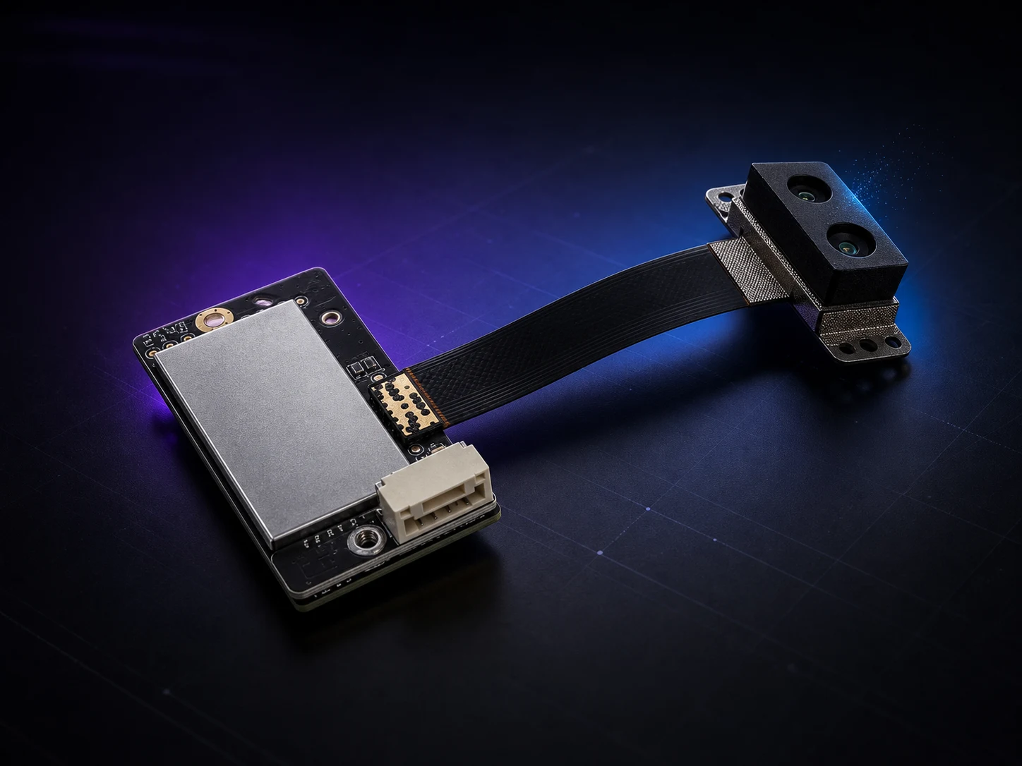
MRP-LD1 module fit
Evaluate MRP-LD1 as a compact UAV obstacle avoidance dToF module—not as a complete collision-avoidance system. Use the verified product facts to screen payload, coverage, data and host fit before mounted testing.
Application direction
MRP-LD1 can provide depth input for a selected direction. It does not turn one mounting position into automatic 360-degree drone collision avoidance.
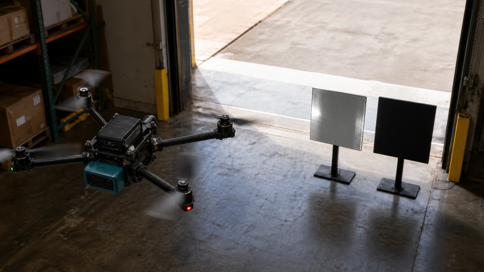
Place the sensing sector around the expected flight direction, then test closing speed, brake margin, thin targets and remaining blind areas.
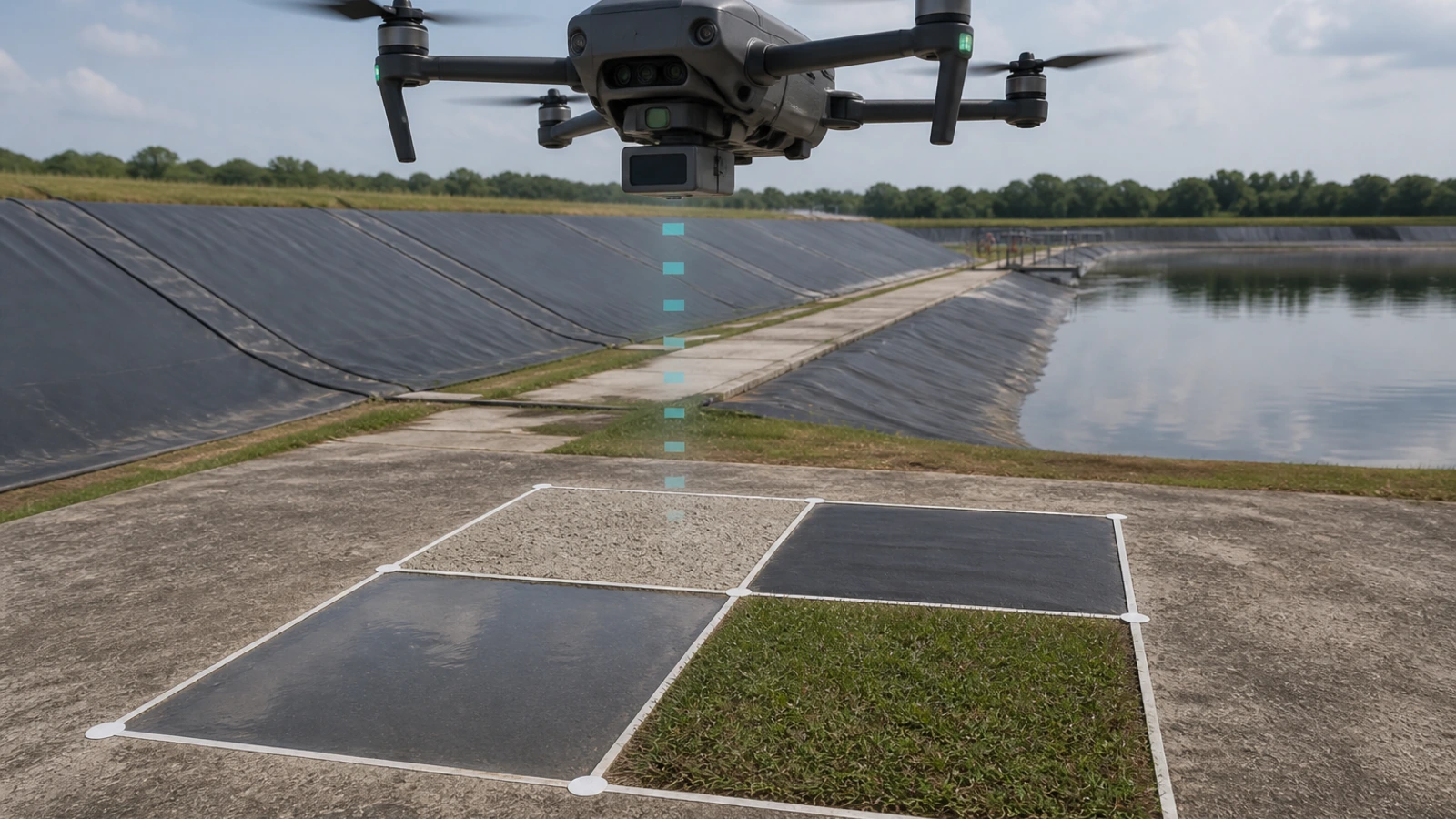
Evaluate altitude and landing-zone input across concrete, vegetation, slopes and surface transitions. Airframe attitude and mounting angle remain part of the test.
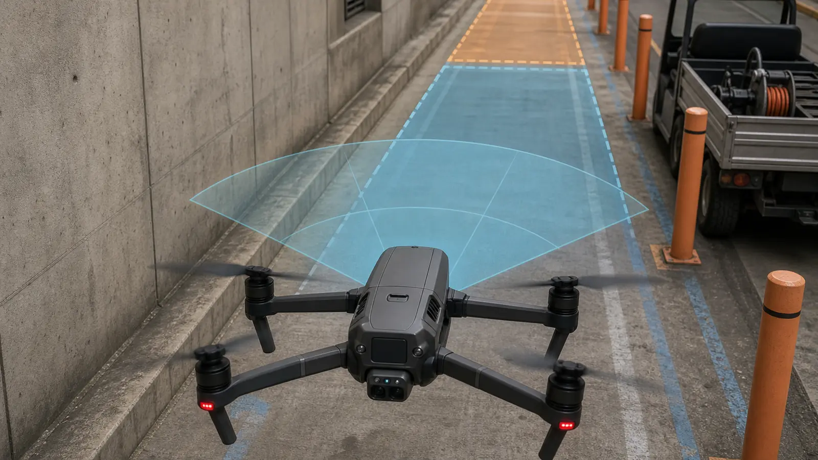
Add separately oriented sensing only where the mission requires it. Document overlap, airframe occlusion and sectors that remain uncovered.
Evaluation path
Keep the evaluation short and measurable. Each step should answer a decision before the team commits to the next build stage.
Share the UAV, sensing direction, target set, distance, lighting, speed, payload and host constraints.
Confirm the product facts, manual, SDK path and representative depth or point-cloud evidence.
Measure alignment, occlusion, vibration, timing and invalid-data behavior on the intended airframe.
Start conservatively, record each handoff and widen the operating envelope only after repeatable evidence.
Engineering and supply support
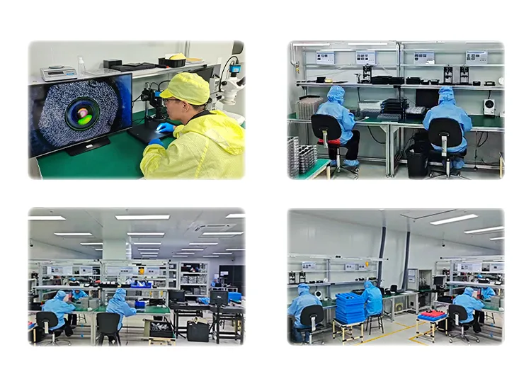
Founded in 2015, Purpleriver develops solid-state dToF technologies and supports B2B teams with product specifications, integration material, sample data and project-specific discussion.
Focused engineering guides
The landing page stays focused on product fit and conversion. These guides carry the detailed information about system behavior, distance and outdoor testing.
Understand the sensing, interpretation, planning and control layers behind an avoidance response.
Read engineering guide ›Connect detection distance, aircraft speed and measured system latency before flight.
Read engineering guide ›Build a repeatable outdoor test around light direction, material, angle and dropout.
Read engineering guide ›Product support
Confirm the product boundary, coverage, timing and test conditions before requesting hardware.
Read the complete dToF LiDAR FAQNo. MRP-LD1 supplies depth information. A host processor, perception logic, decision layer and flight controller must interpret that data and command the aircraft.
Start from the documented 0.2–8 m outdoor baseline and validate the actual target reflectivity, sunlight, mounting and motion conditions. Do not combine it with the separate 0.5–25 m indoor range.
No. The listed field of view is 60° horizontal by 45° vertical. Multi-direction coverage requires mounting and sensor-layout planning.
That depends on speed, closing distance, host latency, control latency and braking dynamics. Calculate and test the complete system margin.
Test the real target size, material, angle and background under representative light direction. Record missed or unstable frames and define the host response rather than assuming one universal result.
The verified interfaces are UART, UVC and UDP, with software support listed for Windows, ARM, Linux and Android.
Share the platform, sensing direction, target materials, operating environment, distance, speed, host, preferred interface, expected quantity and project timing.
Evaluation request
Send the platform, sensing direction, target distance, environment, host, quantity and project timing. These details help match the product, documentation, sample data and next technical discussion.
Name, email and purchase quantity are required. Requirements are optional but help prepare a relevant response.
Drone LiDAR Quote
Share quantity, platform and integration needs. Justin Lu can follow up with quote, sample or technical support details.
Resource unlocked
Your inquiry has been submitted. You can download the requested resource now.
Download resource