Integration evidence brief
1.2W Low Power Class 1 Eye Safe Solid State LiDAR: An Integration Evidence Map
A search for a 1.2W low power class 1 eye safe solid state lidar sounds like one specification request. For an embedded UAV or mobile-robot team, it is four checks: module power, laser-class documentation, solid-state architecture, and the data path the project must prove. Combining them into a headline is how a promising sample becomes an unclear pilot.
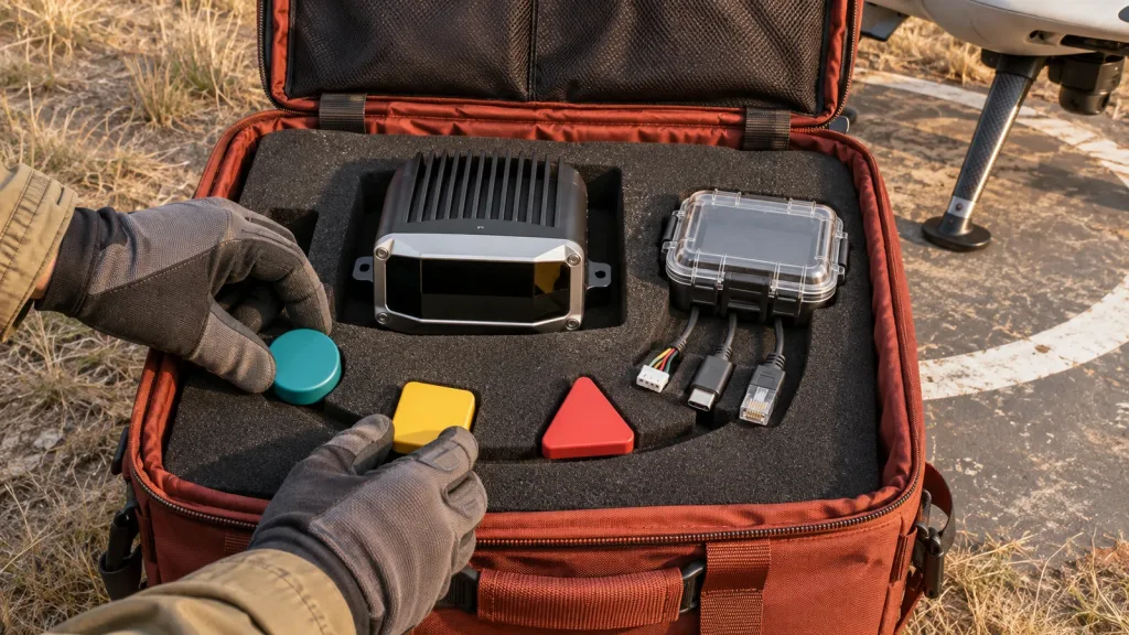
This guide uses the documented MRP-LD1 Drone LiDAR Sensor as a screening example. It does not claim a complete avoidance system, a ROS driver, a flight-controller bridge, or certification for a finished machine. Those are project outcomes that must be documented and tested.
Quick answer
Use the MRP-LD1’s listed 1.2 W, 5 V, Class 1 label, solid-state SPAD dToF architecture, depth/point-cloud output, and UART/UVC/UDP interfaces as module screening inputs. Before a pilot, obtain current documentation, identify the data format and timing, assign ownership of the sensor-to-platform transform, and run a logged target test in the intended mounting and lighting conditions. Product facts alone do not establish a vehicle power budget, system certification, perception logic, controller response, or safe autonomy.
1.2W low power class 1 eye safe solid state lidar: turn each word into a test artifact
The useful purchasing question is not whether all four terms appear in a listing. It is whether the project has an artifact for each term and an owner for the boundary between module and machine.
| Claim | What it can screen | Evidence to retain | Do not infer |
|---|---|---|---|
| 1.2 W / low power | Listed module consumption for a first power discussion. | Current documentation and an installed power-rail measurement. | Total platform draw, endurance, regulator margin, or thermal behavior. |
| Class 1 / eye safe | The module’s published laser-class statement. | Current label/documentation and the project’s applicable review. | Certification or approval of the completed vehicle, enclosure, or use case. |
| Solid state | Compact module architecture at the product boundary. | Published architecture and a mounting/field-of-view drawing. | All-direction coverage, installed shock behavior, or application success. |
| Data output | Whether listed depth/point-cloud output and interfaces fit the host investigation. | Sample data, protocol revision, timing, coordinate convention, and replay. | A native ROS message, flight-controller adapter, or working planner. |
The FDA’s overview of laser products and hazard classes is useful context for why a laser classification belongs in the documentation packet. It is not a substitute for requirements that apply to a finished product in its intended market.
Keep the MRP-LD1 facts exact—and their boundary visible
The following values come only from the Featured-product export. They help decide whether to request an evaluation sample; they do not predict installed performance.
| Published field | MRP-LD1 value | Evaluation use |
|---|---|---|
| Sensing principle | Solid-state SPAD dToF | Identify the sensing approach in the test record. |
| Power / supply | 1.2 W / 5 V | Start a host power-rail review; measure the installed configuration. |
| Weight | 8 g | Record the sensor portion of the payload discussion. |
| Field of view | 60° (H) × 45° (V) | Draw the mounted coverage, blind sectors, and target position. |
| Output | Depth images and 3D point-cloud data | Request representative files and name the host consumer. |
| Resolution / frame rate | 40 × 30 / 10 fps | Use as an input to a project timing test, not a response guarantee. |
| Interfaces | UART, UVC, UDP | Choose one transport and preserve its protocol/version in the record. |
| Listed range baseline | 0.5–25 m indoors; 0.2–8 m outdoors | Set an initial layout, then validate target, angle, ambient light, mounting, and motion. |
| Laser safety label | Class 1 (FDA Recognized Eye-Safe) | Keep vendor documentation with the project review; do not relabel the finished system from this field alone. |
For a transport decision, begin with the site’s UART, UVC, or UDP interface guide. The selected transport changes what the host must parse, log, and recover from.
Application case: an aisle demonstrator with a fixed evidence card
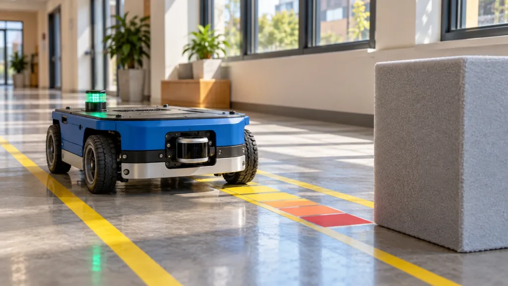
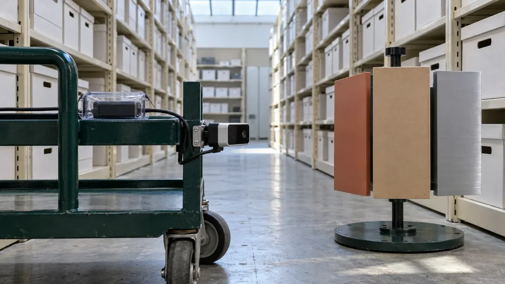
Consider a team evaluating a compact depth sensor above the forward bumper of a supervised aisle vehicle. The aim is not to declare autonomous obstacle avoidance. It is to determine whether sensor data can reach the chosen host in a form the project can interpret consistently.
- Mount the module with a measured sensor-to-body transform and photograph the final bracket position.
- Place a matte panel, reflective panel, and open shelving in the intended coverage area. Record distance, angle, ambient condition, and motion state for every run.
- Log the documented output through the selected UART, UVC, or UDP path alongside host receive time and module configuration/version.
- Replay the recording through the project adapter. The team must explain the frame, timestamp basis, invalid-data handling, and downstream behavior under test.
- Change one condition at a time. Missing, delayed, or ambiguous data is a finding to document, not a gap to hide with a generic range claim.
This small test makes the data boundary observable before planning or controller work begins. For broader ownership, see the sensor-to-flight-controller data contract.
Define the interface, data, and integration boundary
A depth image or point cloud is not automatically a platform-ready message. The official ROS 2 PointCloud2 definition identifies acquisition time and coordinate-frame ID in the header, plus field layout, byte order, point step, row step, data, and density. The MRP-LD1 export does not promise that message type; use those fields as a checklist for the host adapter your project owns.
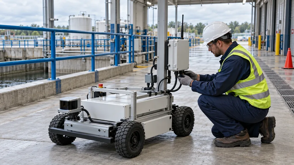
The active ROS REP 105 coordinate-frame convention is helpful for documenting mobile-platform frame relationships. It does not establish an MRP-LD1 ROS implementation. Assign an owner to the transform between physical sensor mounting and platform frame, then record how that transform is measured and revised.
| Host-side question | Record in the test packet | Decision it enables |
|---|---|---|
| Which transport is used? | UART, UVC, or UDP; host OS; protocol revision; cable/network arrangement. | Whether the host collects the documented output repeatably. |
| What does one sample mean? | Dimensions, units, coordinate convention, invalid-value behavior, and documented confidence information. | Whether the consumer can interpret data correctly. |
| When was it observed? | Acquisition timestamp if available, host receive time, clock assumptions, and test-run ID. | Whether latency and replay can be investigated rather than guessed. |
| Where is it mounted? | Bracket drawing, sensor-to-body transform, measurement method, and configuration revision. | Whether points relate to the installed platform consistently. |
| What happens with bad data? | Detection rule, log sample, response owner, and supervised test result. | Whether the project has explicit failure-state behavior. |
If a project needs ROS evidence later, the separate SDK and ROS evidence checklist helps distinguish published module support from a project-specific adapter and replay test.
Common mistakes
- Calling 1.2 W the vehicle power budget. It is a listed module value; the wiring, host compute, regulators, and platform need their own measured budget.
- Turning a module label into a system claim. Retain current module documentation and route the completed machine through the appropriate project review.
- Testing one easy target. A record without material, angle, light, and motion cannot explain why results change.
- Assuming point-cloud output means ready-made autonomy. Define the data contract, frame ownership, and consumer before calling the system integrated.
- Hiding the no-data case. Include stale, malformed, missing, or out-of-coverage data and name the owner of the response.
RFQ and evaluation checklist
- State the platform, mounting location, coverage area, and working-distance scenario.
- Ask for current MRP-LD1 documentation, protocol material, and representative output.
- Name the candidate interface, host OS, and preferred test format.
- Record configuration, firmware/protocol revision, target materials, angle, ambient conditions, and motion.
- Define ownership of the sensor-to-body transform and invalid/stale-data behavior.
- Separate module facts from work required for the completed vehicle or robot.
- Request an evaluation sample or project-specific quote only after the evidence card matches the intended test.
Turn the headline into an evaluation record
Share the platform, mounting position, working-distance scenario, host system, preferred interface, and expected project timing. Purpleriver can provide current product documentation and discuss an evaluation sample, SDK resources, sample data, or a project-specific quote.
Request an evaluation discussion or review documentation resources.