Quick answer: A LiDAR SDK Windows Linux Android ARM evaluation should not end with “the device was detected.” Before a field pilot, create one versioned portability evidence pack: a defined scene, raw captures, a manifest, expected decoded summaries, host logs, and a reconnect test. Run the same contract on the Windows bench, the Linux/ARM companion computer, and the Android diagnostic host. That turns a platform list into reviewable evidence without assuming a native ROS package, autopilot driver, or complete avoidance system.
LiDAR SDK Windows Linux Android ARM: define “works” before you port
An embedded team may reasonably want a Windows bench tool, a Linux/ARM companion computer, and an Android service utility around the same depth module. The unhelpful question is “Does the SDK work on all three?” The useful question is: Can each host reproduce the same declared observation contract and make its failures visible?
Start with the purpose of each host. Windows can be the controlled capture and review workstation. Linux/ARM can be the intended embedded runtime. Android can be a technician’s cable-side diagnostic or a deliberately scoped field utility. Those are different jobs, so success should not mean that their interfaces look identical. It should mean that each host can prove the agreed input, output, timing description, error state, and software version for its job.
That distinction matters when an evaluation moves toward a UAV or robot. A valid depth stream is not automatically a navigation input, and a navigation input is not automatically a complete safety function. The published PX4 Collision Prevention guidance, for example, treats sensor coverage, data availability, delay, and vehicle configuration as part of the behavior. Treat platform porting as a separate engineering gate before connecting it to such a downstream function.
Use a portability decision chart, not a logo checklist
| Question | Evidence that answers it | What it does not prove |
|---|---|---|
| Can the host see the connected device? | Connection record, device/interface identity, power state, and permission result. | That the correct data mode, frame layout, or application API is usable. |
| Can the host acquire the intended stream? | Selected transport, requested mode, observed format, resolution, frame count, and raw sample. | That every advertised transport or mode is available on every host. |
| Can the software interpret it consistently? | Versioned decoder, units, dimensions, byte order, invalid-value rule, and expected-summary comparison. | That the measurement is fit for a particular aircraft, target, or safety claim. |
| Can the runtime survive a field interruption? | Controlled unplug/reconnect, timeout, restart, log, and operator-visible recovery record. | That the vehicle has an approved response to sensor loss. |
| Can the result be handed downstream? | Named coordinate frame, timestamp origin, freshness rule, coverage statement, and receiving-interface test. | Native autopilot, ROS, or MAVLink support unless separately documented and tested. |
Do not average these gates into a single “compatibility score.” A team may accept a Windows-only review tool while rejecting an embedded runtime that cannot preserve timestamps or reconnect predictably. Mark hard blockers first, then compare preferred features.
Build one capture contract that can travel between hosts
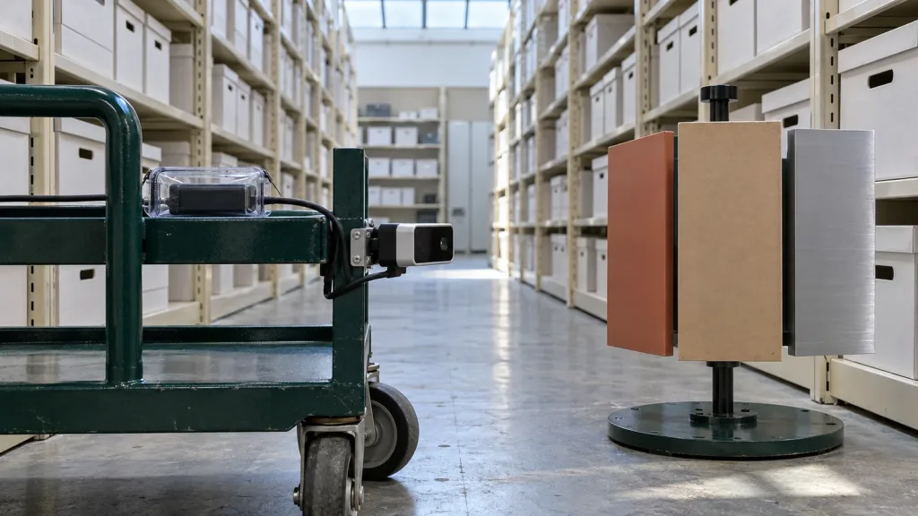
A portability evidence pack is a small, repeatable test bundle—not a marketing screenshot. Freeze one representative bench or field scene and keep the sensor mount, distance, target materials, illumination note, and power arrangement visible in the record. Capture a short raw sequence through the selected path, then save a human-readable manifest beside it.
The manifest should name the module and firmware supplied for the evaluation, host model and OS build, application/driver/decoder version, selected UART/UVC/UDP path, requested and observed stream mode, depth units, frame dimensions, byte order, invalid or confidence handling, timestamp origin, coordinate convention, and checksum of the raw capture. Add an expected summary: for example, frame count, valid-pixel count, minimum/maximum values after declared filtering, and the expected behavior when the stream is absent. The goal is comparison, not an invented accuracy certificate.
Keep raw data distinct from a rendered depth picture. A colorized viewer is useful for an engineer, but it can hide scaling, clipping, dropped frames, or an all-invalid payload. The site’s point-cloud dataset evaluation guide is a useful companion for deciding which metadata and samples make a dataset reviewable. For the first host contract, also decide whether the consumer needs a depth image, a point cloud, or both; see the related depth-map versus point-cloud guide.
Record the host boundary, not just the cable name
UART, UVC, and UDP describe possible transports; they do not, by themselves, describe an application contract. Document the selected path and prove only that path first. The site’s UART, UVC, or UDP interface guide can help frame the transport choice, but the exact mode, framing, driver scope, and recovery procedure still belong in the evidence pack.
On a Windows test station, a UVC-compatible mode may be served by the system UVC driver; Microsoft’s UVC driver overview explains that compliant UVC devices can use the supplied driver and exposes capability information through the UVC model. Record the observed device and selected mode rather than assuming every capture format is equivalent. On Android, the official USB-host overview shows why host support, enumeration, permission, interface, and endpoint selection should be deliberate test items. These documents support a validation plan; neither establishes an MRP-LD1 app, a specific Android host result, or a supplied driver.
Evaluate the MRP-LD1 as a component candidate, not a finished stack
The Featured MRP-LD1 Drone LiDAR Sensor is a compact candidate for a host-integrated depth evaluation. Its listing names Windows, ARM, Linux, and Android in software support and names UART, UVC, and UDP interfaces. That is a sensible reason to ask for the evaluation artifacts above. It is not a statement that a particular OS image, framework, application, autopilot, or native ROS package is included.
| Verified product field | Published MRP-LD1 value | Portability question to keep open |
|---|---|---|
| Ranging/scanning principle | Solid-state SPAD direct time of flight (dToF) | Which exported representation and units will each host consume? |
| Output | Real-time depth images and 3D point-cloud data | Which output is the common capture artifact, and how are invalid points marked? |
| Resolution and frame rate | 40 × 30; 10 fps | How will the team measure acquisition-to-consumer age and dropped frames? |
| Field of view | 60° horizontal × 45° vertical | What mounting frame and actual covered sectors are declared downstream? |
| Interfaces | UART, UVC, UDP | Which one is in scope for each host and which format/version is recorded? |
| Software support | Windows, ARM, Linux, Android | What exact host, OS build, application, and recovery test pass the project gate? |
| Published range baseline | 0.5–25 m indoors; 0.2–8 m outdoors | Which scene, target, angle, and ambient-light matrix will the project use? |
| Ambient-light baseline | 80 Klux | How will the final window, mounting, sun direction, and target reflectivity be evaluated? |
Keep the component’s published values and the host project’s results in separate columns. The MRP-LD1 listing gives a 60° × 45° field of view, for example; it does not define an aircraft body transform, an obstacle-sector policy, or an approved vehicle response. Use the documentation resources to request current material, then put unverified questions into the evaluation plan rather than filling the gaps with assumptions.
Run a three-host matrix with the same pass criteria
Use the exact same evidence-pack version on every host. Allow the application UI to differ, but require a comparable machine-readable summary. That stops a good-looking desktop preview from masking a different decoder or data age on the embedded runtime.
| Host role | Minimum demonstration | Failure exercise | Decision output |
|---|---|---|---|
| Windows bench workstation | Identify the selected device/mode; acquire the reference scene; save the raw capture and manifest. | Change cable or power once; capture the application and system record of loss and recovery. | Reference capture and decoder baseline. |
| Linux/ARM companion computer | Acquire or replay the same declared output; compare expected summary, timestamps, and frame interpretation. | Restart the consumer and interrupt the selected path; prove the freshness/unknown state is not silently reused. | Embedded runtime readiness or a documented blocker. |
| Android diagnostic host | Record host capability, connection permission, selected interface/endpoint, and a short diagnostic capture if the project needs it. | Detach and reattach the device; make the permission and recovery outcome visible to the technician. | Field-service scope accepted, deferred, or rejected. |
For Android, do not reduce the gate to “the phone charges the device” or “an app saw something.” The Android USB-host documentation separates discovery, user permission, interface selection, and endpoint communication. Record which of these is needed for the project’s utility. For an ARM companion, record the actual image and hardware revision; “ARM support” is not a substitute for a reproducible host configuration.
Make the data handoff testable before it reaches a vehicle controller
A field pilot may have a Windows tool only for commissioning, an ARM companion computer in the vehicle, and an Android device for diagnostics. The portability pack must therefore make it obvious which output is raw evidence and which output, if any, enters a control-facing adapter. Name the data owner, coordinate frame, timestamp source, valid range policy, invalid-data state, coverage/FOV statement, update/freshness rule, and timeout reaction.
If a project deliberately translates host-side observations to MAVLink, read the applicable MAVLink common-message definition and preserve its exact field semantics in the adapter design. If it uses PX4 collision prevention, PX4’s documentation says a companion or external sensor needs to supply obstacle information and makes coverage and missing data operationally significant. Neither document makes this module a plug-in autopilot sensor; it describes the receiving system’s contract.
The existing LiDAR sensor data-contract guide is a practical internal checklist for that review. A healthy design can say “unknown,” “stale,” “not covered,” and “valid” separately. A design that reuses a last-good value after a transport break may appear stable at a viewer while giving the downstream system a false impression of the current scene.
Worked case: one doorway scene, three hosts, one review meeting
Illustrative engineering scenario—not a customer result: A UAV team wants a compact depth module for an indoor doorway approach study. Windows is used at the lab bench; a Linux/ARM companion is planned for the aircraft; an Android device is requested for cable-side diagnostics. The team does not claim obstacle avoidance yet.
They mount the module on a fixed stand and place a matte panel, a dark fabric target, and a reflective strip at documented distances. On Windows, they save a short raw capture, a manifest, and an expected-summary file. The summary lists frame dimensions, declared units, count of usable samples under the project rule, and the time basis the tool reports. It also contains a photo of the test arrangement—not as a performance proof, but so the next host can repeat the scene.
On Linux/ARM, the team runs the same capture or replay through the intended consumer. A difference in byte order, scaling, frame ordering, or invalid-value handling becomes a review item instead of a hidden platform difference. They disconnect the selected interface, confirm that the consumer announces an unknown/stale input rather than continuing the old scene, then record restart behavior.
On Android, the scope is narrower: a technician must confirm attachment, permission, identity, and a short diagnostic record before a bench test. The team tests detach/reattach and saves the outcome. Only after all three outputs can be compared does it choose whether to build a controller-facing adapter. The next phase would separately validate mounting, coverage, delay, vehicle configuration, and response on the final system.
Common portability mistakes
- Treating a platform list as an application guarantee. Record the exact host, OS image, selected interface, application version, and observed behavior.
- Comparing screenshots instead of raw evidence. A viewer can conceal scale, clipping, invalid samples, or time drift.
- Giving each host a different test scene. Keep one defined scene and reference capture so a difference is attributable.
- Calling a cable protocol an SDK contract. UART, UVC, and UDP still need mode, framing, units, version, and recovery evidence.
- Assuming a supplied OS driver proves the desired payload format. Detection and transport are only early gates.
- Skipping the reconnect test. A field cable, power cycle, or permission reset is part of real diagnostic behavior.
- Hiding no-data under the last good frame. Preserve unknown, stale, and valid as separate states.
- Assuming “software support” means native ROS, MAVLink, or autopilot support. Ask for the actual API and build the adapter only if it is in scope.
- Porting before freezing the decoder contract. If dimensions, units, byte order, timestamps, and invalid values move, every host can be “right” in a different way.
- Promoting a bench capture into a flight result. Mounting, target, illumination, coverage, timing, controller, and response still require system-level validation.
Evaluation and RFQ checklist
Send a supplier and your internal software team a bounded request. It should make it possible to evaluate the component without promising features that have not been documented or tested.
- target application, indoor/outdoor scene, working distances, target materials/angles, illumination, and installed window or mount assumptions;
- the intended role of Windows, Linux/ARM, and Android, including exact host models and OS builds where already chosen;
- which UART, UVC, or UDP path is in scope for each host and which paths are explicitly out of scope for the pilot;
- current protocol/API/SDK documentation, firmware version, sample raw data, decoder examples, and revision/change-notification expectations;
- depth or point-cloud representation, dimensions, units, byte order, invalid values, confidence fields, timestamps, and coordinate conventions to be established;
- the expected portability evidence pack: raw captures, manifest, reference scene, checksums, decoded summary, logs, and reconnect record;
- power, cabling, connector, bandwidth, host storage, thermal, mounting, and field-service questions not answered by the public listing;
- the downstream consumer, if any, plus required coverage, freshness, timeout, and unknown-data behavior; and
- acceptance criteria that separate component data evidence from vehicle behavior, safety assessment, and operational approval.
Start with a Capture Contract, Not a Compatibility Assumption
Share your target host roles, selected interface, OS versions, application scene, required output, and the field interruption you need to handle. Purpleriver can help you compare those evaluation questions with the MRP-LD1’s published parameters and prepare an evidence-focused sample request.