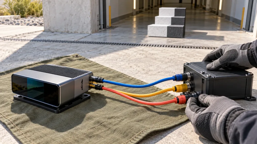
Solid State LiDAR with SDK / ROS Support: A Buyer’s Evidence Checklist
Solid state LiDAR with SDK / ROS support is not a checkbox a buyer should accept from a product listing. A useful integration claim has an evidence trail: the sensor’s documented output, the SDK or driver source, the project’s message contract, the mounted coordinate frame, and a replayable record of normal and bad data. Without that trail, a compact LiDAR may be a promising evaluation candidate, but its ROS handoff is still an engineering task—not a delivered capability.
This guide gives robotics teams a procurement-ready way to ask for that evidence before they spend a sprint on an adapter or schedule an on-platform pilot.
Quick answer
Ask for a five-part evidence bundle: documented sensor output, current SDK or protocol material, an explicit host-to-ROS message mapping, a mounted-frame record, and replay samples that include invalid or missing data. For the MRP-LD1 Drone LiDAR Sensor, the Featured-product record documents depth images and 3D point-cloud data, UART/UVC/UDP interfaces, and Windows/ARM/Linux/Android software support. It does not by itself document a native ROS package, a PointCloud2 publisher, or a robot-navigation integration. Treat those as questions to verify in the project.
- Separate published module facts from the host software your team must own.
- Require a sample capture and an unambiguous data/protocol description.
- Write down timestamps, frames, units, invalid-data behavior, and conversion ownership.
- Replay normal, degraded, stale, and missing data before connecting a downstream behavior.
- Approve only the narrow integration boundary that the evidence actually supports.
1. A solid state LiDAR with SDK / ROS support needs a defined boundary
“SDK support,” “Linux support,” and “ROS support” describe different things. An SDK might expose samples, a protocol, a library, or a viewer. Linux support might mean that a host can enumerate a device or run supplied software. A ROS-ready path adds another layer: somebody must turn sensor output into a defined message with usable timing, coordinate-frame, field-layout, and health semantics.
The official ROS 2 PointCloud2 message definition makes that distinction concrete. Its header carries acquisition time and a coordinate-frame ID; its remaining fields describe the point layout, byte order, point/row strides, binary data, and whether all points are valid. That is a useful review checklist, not a claim that every point-cloud sensor or product automatically publishes PointCloud2.
Likewise, an active ROS coordinate-frame convention defines shared mobile-platform semantics and a tree in which each frame has one parent. Before accepting a ROS claim, ask who owns the fixed transform from the installed sensor to the robot body and where that transform is recorded. A generic “driver available” statement does not answer either question.
Use the site’s Windows and Linux LiDAR validation guide for host-side preparation. This article focuses on the evidence that must cross the next boundary: from a documented module output into a project-owned robotics message and frame contract.
2. Use a five-part evidence bundle before you call the handoff ready
The table is an acceptance-planning tool. It does not certify a sensor, approve a vehicle, or replace the responsible team’s risk, controls, and application testing.
| Evidence bundle item | What the team should inspect | What cannot be inferred | Practical gate |
|---|---|---|---|
| 1. Sensor-output record | A raw or exported sample, declared mode, units, resolution, valid/invalid meaning, and capture conditions. | A visually plausible point cloud does not establish a stable application result. | Can another engineer open the sample and identify exactly what each field represents? |
| 2. SDK or protocol provenance | Versioned documentation, supported host environment, a repeatable install path, and named owner for questions. | Operating-system support does not prove a ROS package or long-term API compatibility. | Can the team reproduce one documented acquisition without reverse engineering? |
| 3. ROS message contract | Which message is produced, the timestamp source, frame ID, field mapping, units, byte ordering, and invalid-data policy. | “Point-cloud output” alone does not specify PointCloud2 layout or downstream usability. | Can a recorded source sample be converted and checked against the written mapping? |
| 4. Mounted-frame contract | Sensor position/orientation relative to the body, transform publisher/owner, mounting revision, and physical sign convention. | A correct bench stream does not prove that installed geometry is understood. | Can the project identify the sensor frame and transform it consistently into the robot body frame? |
| 5. Replay and fault record | Normal, sparse, stale, malformed, invalid, and missing-data samples; expected adapter state; log fields. | A demo with only clean data does not define behavior when data is late or unavailable. | Can the adapter expose “unknown” without silently turning it into a clear scene? |
The point of the bundle is ownership. The supplier may document a module and provide materials; the project still needs a named owner for the driver or adapter, transforms, message choices, downstream consumer, and acceptance test.
3. Screen the documented module facts separately from ROS claims
The following is a faithful screening table for the available Featured product. It is deliberately not a ROS compatibility table.
| Published field | MRP-LD1 documented value | How to use it in an SDK/ROS review |
|---|---|---|
| Product | MRP-LD1 Drone LiDAR Sensor | Use the current product page and requested documentation as the source for the evaluation package. |
| Sensing architecture | Solid-state SPAD dToF | Describe the module accurately; do not use the architecture label as evidence of a middleware driver. |
| Output | Depth images and 3D point-cloud data | Ask which output mode and field interpretation the project will convert, retain, and replay. |
| Interfaces | UART, UVC, UDP | Select one initial transport and document the reader, packet/frame boundary, and recovery behavior. See the UART, UVC, or UDP interface guide for an interface-level comparison. |
| Listed host support | Windows, ARM, Linux, Android | Confirm the exact supplied materials and target environment; this listing does not assert a ROS distribution or native ROS package. |
| Resolution and frame rate | 40 × 30; 10 fps | Use as a starting point for sample-record and host-load planning, then test the actual chosen mode and scene. |
| Field of view | 60° × 45° | Measure the installed view and any occlusion in the actual robot geometry rather than inferring coverage from a catalog field alone. |
| Mass and power | 8 g; 5 V supply; 1.2 W | Include the module in the integration budget, then account separately for mounting, cabling, and host hardware selected by the project. |
| Listed ranging baseline | 0.5–25 m indoors; 0.2–8 m outdoors | Keep the scene, target, angle, and ambient conditions in the test record; use no blanket application-performance conclusion. |
Published product facts are useful for screening an evaluation. They do not settle how a driver handles frame timestamps, invalid samples, coordinate transforms, application logic, or deployment approval.
4. Illustrative case: an AMR aisle pilot that starts with replay, not navigation
Imagine a robotics team assessing a compact sensor for an indoor mobile-robot aisle. The first narrow question is not “can this sensor navigate the warehouse?” It is: “Can our chosen host reliably capture one documented output mode, convert it into our declared message/frame contract, and preserve the difference between valid, invalid, and missing observations?”
The team mounts the candidate sensor on a non-moving test fixture at the intended height and records a nominal aisle target, a near object, an angled surface, and a deliberate data interruption. It retains the raw capture, adapter output, transform revision, host logs, and the condition notes. Only after that package is reviewed does the team decide whether it is worth connecting the stream to a mapping or perception experiment.
This scope makes results useful even when the answer is “not yet.” It exposes whether the next work item is a protocol question, a transform correction, a host limitation, a test-data gap, or a different sensing approach. For output vocabulary, the site’s depth-map versus point-cloud guide can help the team state which representation its consumer actually needs.
5. Make the interface, data, and integration handoff reviewable
Start with one transport and one accountable adapter
Choose the initial UART, UVC, or UDP path from the documented module interfaces based on the host and evidence you need. Name the component that reads the source data and the owner of that component. Record the version of the protocol material or SDK used for the trial. If a bridge turns source data into ROS messages, label it as a project adapter unless its supplied status and version have been separately verified.
Write the message contract before tuning downstream behavior
For a point-cloud path, record the acquisition timestamp source, frame ID, fields, units, endianness, point and row layout, and treatment of invalid points. The PointCloud2 definition is useful because it explicitly distinguishes layout and validity information from the binary payload. A message that merely renders in a visualization tool may still be unsuitable for the intended consumer if these choices are unknown.
Make the mounted transform a controlled artifact
Document the sensor’s physical pose relative to the robot body, who publishes or owns that relationship, and which mount revision the record applies to. ROS REP 105 explains why shared frame conventions and clearly defined authorities matter when components must interoperate. A frame error can make a technically valid stream unusable in the installed system.
Replay before you attach a decision
Keep source captures and adapter output for ordinary data plus at least one condition where data is invalid, delayed, malformed, or missing. The 2025 SPAD dToF ranging-precision research analyzes how detector dead time, photon flux, pulse width, and time quantization can affect ranging information. It is not an MRP-LD1 performance result. It is a sound reason to preserve the physical and timing conditions of any evaluation rather than generalizing from a single attractive capture.
Request current protocol material and sample data through the site’s documentation resources, then put the received version and its test scope into the project record.
6. Common mistakes that turn “ROS support” into rework
- Equating Linux with ROS: an operating-system listing is not proof of a driver, package, message mapping, or transform design.
- Calling a visualization a handoff test: rendering points does not show that timestamp, fields, units, invalid samples, and frame ownership are correct for the intended consumer.
- Leaving the mounting transform implicit: a sensor frame needs a recorded relationship to the body frame and an owner who updates it when hardware moves.
- Testing only clean captures: stale or unavailable data must stay visible as such; it should not silently become an apparent clear scene.
- Mixing product facts and project assumptions: a listed interface or output does not specify your host, bridge, planner, controller, or acceptance rule.
- Approving a broad application too early: approve a narrow capture-and-conversion boundary first, then expand the evaluation one evidence-backed step at a time.
7. RFQ and evaluation checklist for SDK / ROS evidence
- Exact target host, operating system, architecture, and test owner.
- Requested output mode, sample capture, current protocol/SDK version, and license or delivery path where applicable.
- Chosen transport: UART, UVC, or UDP; reader component; source-frame and packet-boundary expectations.
- Intended message type, timestamp source, frame ID, units, field layout, invalid-data convention, and adapter owner.
- Installed mount drawing or measurement, sensor-to-body transform, transform owner, and revision-control method.
- Representative target geometry, materials, distance, orientation, ambient conditions, and capture conditions.
- Normal, invalid, delayed, malformed, and missing-data samples plus expected log and adapter behavior.
- The next narrow decision: bench acceptance, replay acceptance, constrained pilot, or a request for more documentation—never an unqualified system claim.
Turn your integration question into an evidence request
Send Purpleriver the target host, intended output mode, chosen interface, robot-frame information, and the sample/replay evidence you need. We can help you start an MRP-LD1 evaluation with documented module facts while keeping project-owned ROS work explicit.
Contact Purpleriver about an evaluation and include your requested test boundary.