Drone Altitude Hold dToF Sensor: A Near-Ground Evidence Plan
A downward-looking sensor can be a useful input to a UAV altitude-control evaluation, but a product specification is not a hover-test result. Before a team routes a dToF reading to a host, it needs evidence about the installed view, the ground-return record, data age, invalid values, and the host-side interpretation. This guide gives a practical acceptance card for that work.
Quick answer
For a drone altitude hold dToF sensor evaluation, begin with a restrained or controlled near-ground evidence card—not an unbounded flight claim. Record the sensor mount and unobstructed view; capture representative ground returns at declared heights and surface conditions; preserve raw data, timestamps, validity rules, and the host conversion; then use the flight stack’s current documentation to define a project-specific, tested maximum and bounded test procedure.
What this evidence plan proves—and does not prove
The task is to show that a particular downward installation produces an understandable, repeatable data record in the scene the project intends to test. It does not prove an aircraft will hold altitude, land safely, avoid obstacles, or work in every surface and lighting condition.
The current ArduPilot rangefinder documentation describes rangefinders as possible inputs for ground-distance, precision-landing, and altitude-control uses. It also warns that a configured maximum must be a tested, appropriate value. That is valuable host-stack guidance, but it is not evidence that any particular dToF module is natively supported or correctly configured for a reader’s aircraft.
The current WooCommerce Featured product is the MRP-LD1 Drone LiDAR Sensor. Its listing says it supplies depth images and 3D point-cloud data; it does not describe a complete altitude-hold system. The host processor, perception logic, flight controller, vehicle setup, and validated response remain part of the wider project.
Choose the first test by the evidence you need
| Starting condition | First useful test | Record before progressing | Do not infer |
|---|---|---|---|
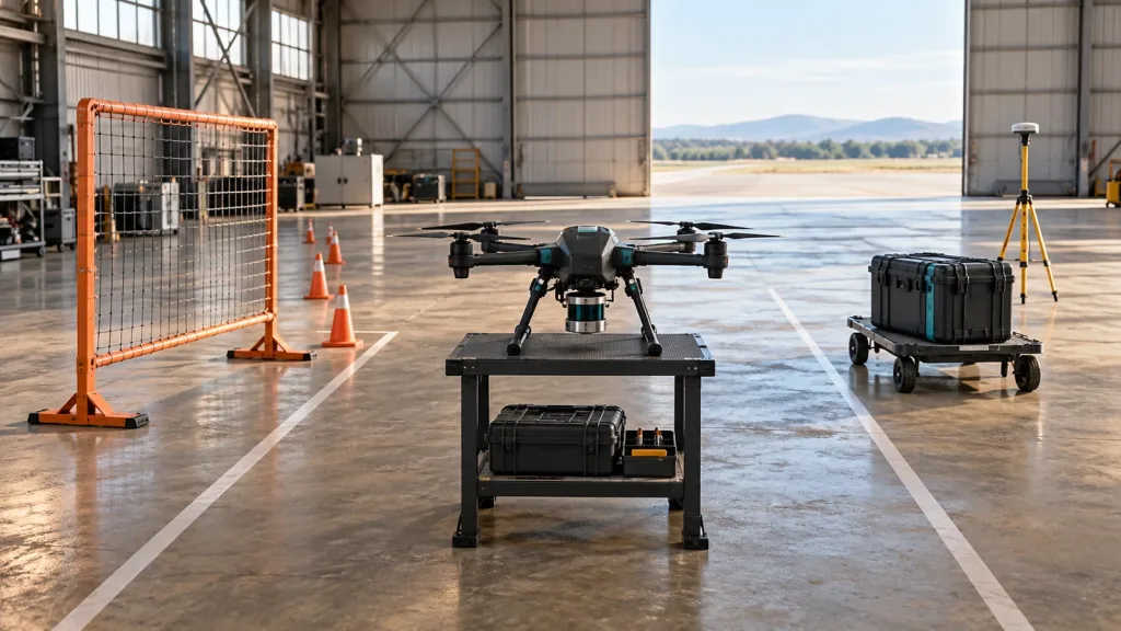
| Module is only on a bench | Fixed-height, downward-looking target capture | Mount orientation, optical-centre height, target surface, illumination, raw output, and decoded value | That a bench distance is a flight-ready altitude input |
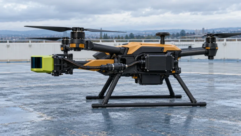
| Module is mounted on an airframe | Propellers stopped: check landing gear, arms, wiring, and body shadowing across the intended downward view | Aircraft revision, bracket geometry, photos, view boundary, and the affected height region | That the published field of view is unobstructed after installation |
| Host conversion is planned | Replay a saved capture through the intended host path | Units, min/max rules, source timestamp, receipt timestamp, validity treatment, orientation, and log output | That UART, UVC, or UDP alone creates a flight-controller integration |
| Controlled hover evaluation is proposed | Use the project’s safety process and declared boundary to test only the documented input path | Test owner, test area, firmware/configuration revision, expected fallback, stop rule, and observations | That one bounded result transfers to all terrain or operating modes |
Published MRP-LD1 facts to use as screening inputs
Use exact listed values to decide whether a sample is worth evaluating. Treat them as a starting boundary for a project test, not as a substitute for its acceptance rule. For a broader mounting discussion, see the site’s dToF LiDAR field-of-view fit test.
| Published MRP-LD1 item | Listed value | How it belongs in the evidence card |
|---|---|---|
| Architecture | Solid-state SPAD dToF | Record it as the candidate sensing approach; do not turn the architecture name into a promise of control performance. |
| Mass and power | 8 g; 1.2 W; 5 V | Check the actual airframe power and mounting design with the project owner. |
| Listed range baseline | Indoor: 0.5–25 m; outdoor: 0.2–8 m | Declare the proposed heights and conditions; capture representative data instead of copying a maximum into configuration. |
| Field of view | 60° horizontal × 45° vertical | Draw the installed downward envelope and inspect it for gear, arms, cables, and ground-region coverage. |
| Output and rate | 40 × 30; 10 fps; depth images and 3D point-cloud data | Define which output is being evaluated, how it is reduced or translated, and how freshness is measured. |
| Interfaces | UART, UVC, UDP | Select the transport only after checking current protocol material, host hardware, logging, and recovery behavior. |
| Software support | Windows, ARM, Linux, Android | Confirm the exact host and current materials required for the chosen implementation. |
Build the downward ground-return acceptance card
Place a card beside every capture. It makes a later decision reviewable and stops a plausible-looking number from losing its context. A useful card answers five questions:
- Where is the sensor? Save the airframe revision, bracket revision, optical-centre position, facing direction, and photos of what can block the lower view.
- What was below it? Name the surface material, texture, slope, target size, illumination condition, and measured height reference. Do not label a surface “representative” without saying why.
- What did it output? Keep the original capture, decoded output, firmware/protocol version if supplied, the chosen output type, and the rule used to label a value usable, invalid, stale, or absent.
- When was it true? Separate sensor acquisition time, host-receipt time, and log-write time. A value that arrived late should not silently look like a fresh ground observation.
- How will the host interpret it? Record units, min/max handling, orientation, transform, any filtering, and the expected behavior when data is unavailable.
This record is intentionally more specific than a generic feature checklist. It joins a particular optical installation to a particular ground scene and a particular data-handling path.
Keep the data and host handoff auditable
When a project translates data into a flight-stack message, it must preserve meaning rather than merely send a number. The official MAVLink DISTANCE_SENSOR definition includes time, minimum/maximum/current distance, facing direction, covariance, horizontal and vertical field of view, a custom vehicle-body-frame orientation, and signal quality. It is a useful checklist for a host-side mapping; it does not establish that MRP-LD1 emits MAVLink natively.
A team working with directional obstacle information should also understand the official MAVLink OBSTACLE_DISTANCE definition, which distinguishes angular sectors, explicit unknown/not-used values, angle offsets, and a body-front-aligned frame. A single downward ground reading and an obstacle-sector representation answer different questions; do not convert missing data into either “ground present” or “clear space” without a declared rule.
The MRP-LD1 listing names UART, UVC, and UDP. Use the site’s UART, UVC, or UDP interface guide to frame the transport choice, and the depth map versus point cloud guide to clarify what the selected host must handle. Before committing to a design, request current protocol, SDK, firmware, and sample-data material through the documentation resources.
Illustrative case: compare three ground surfaces before a controlled hover test
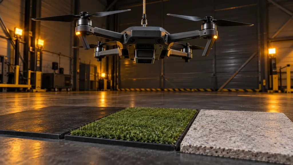
Illustrative evaluation scenario—not a customer result or a product-performance claim: a UAV team mounts a compact dToF module beneath a small test airframe and proposes a near-ground altitude-input evaluation. Before power-on flight work, the team holds the aircraft at three declared heights above a matte landing pad, short grass, and a textured light concrete panel. The propellers remain stopped for these captures.
For every surface-height combination, the team saves the bracket revision, a side photo showing the optical path, a measured height reference, ambient condition, raw capture, decoded record, value age at the host, and its validity outcome. The team repeats any condition after a small airframe or mounting change instead of assuming the earlier capture still applies.
Only when the project can explain the downward view and replay the selected data through its intended host path does it consider a controlled, project-approved test. The outcome is a traceable decision about what to test next—not a universal altitude-hold recommendation.
Common drone altitude hold dToF sensor mistakes
- Using a listed maximum range as a configuration value. A listed envelope screens a candidate; a host setting still needs a tested value for the intended integration.
- Ignoring the installed downward view. Landing gear, arms, wiring, vibration isolation, and a changed bracket can alter the visible ground region.
- Saving only a processed distance. Retain raw output and the decode path so a later reviewer can distinguish sensing, translation, and host behavior.
- Mixing timestamps. Sensor time, host-receipt time, and log-write time are not automatically interchangeable.
- Calling an interface a native autopilot driver. The Featured listing identifies UART, UVC, and UDP; it does not claim a particular autopilot implementation.
- Testing one surface and declaring a capability. The target, height, angle, light, mounting, and movement context belong in the acceptance rule.
- Turning a sensor test into a safety claim. System behavior remains dependent on the wider aircraft, its controller, its configuration, and its own safety process.
RFQ and evaluation-sample checklist
Send a request that exposes the real integration questions early. The goal is not to guarantee an outcome before testing; it is to obtain the materials and constraints needed to run an honest evaluation.
| Include or request | Why it matters |
|---|---|
| Aircraft outline, sensor optical-centre location, downward mount angle, and bracket constraints | Lets the supplier and project team discuss the actual installed view rather than a generic sensor orientation. |
| Proposed heights, ground surfaces, lighting conditions, and motion context | Defines the first acceptance card and avoids substituting a broad claim for a declared test scene. |
| Selected output, host platform, transport, logging method, and freshness rule | Makes conversion, timestamp, and recovery work visible before a flight date is committed. |
| Current protocol, data-format, SDK, firmware, and sample-data materials | Gives the team source material to inspect for the chosen interface and host implementation. |
| Published parameters to compare | Keeps the evaluation tied to the listing’s mass, power, range, FOV, output, rate, interfaces, and supported software platforms. |
| Project owners, stop rule, and record location | Creates a reproducible handoff among mechanical, perception, controls, test, and purchasing roles. |
Prepare a better dToF evaluation request
Share the proposed UAV mount, working heights, intended ground surfaces, host platform, preferred interface, and the records your team needs. Purpleriver can help compare those requirements with the MRP-LD1’s published parameters and identify the documentation needed for an evaluation.