dToF LiDAR module evaluation goes wrong when a team treats a data sheet as proof that the module will see the required area after it is bolted to a real UAV. A listed field of view, range, weight, and interface are useful starting facts. They do not describe the aircraft's installed blind areas, the host's data handling, or whether a project-defined target remains usable in the intended scene.
This guide is for the UAV engineer or technical buyer who needs to decide whether a compact depth module belongs in an evaluation sample plan. It turns product facts into a practical mount-fit record: what to plot, what to capture, and what to ask before a bracket or software path is approved.
| Quick answer | Approve a dToF module for evaluation only after the proposed mount, the application-relevant coverage, the raw output, and the host handoff have all been checked against the same written test card. |
|---|---|
| Best fit | Prototype teams comparing compact UAV sensing modules for depth-aware measurement, altitude-related experiments, terrain-following investigation, or obstacle-awareness research. |
| Decision rule | If the supplier listing cannot be connected to a physical mounting sketch and a repeatable acceptance capture, leave it as an open evaluation question—not a promised flight function. |
What a dToF LiDAR module listing can—and cannot—establish
A module listing can establish the published design envelope. That is valuable because it allows a buyer to reject an obvious mismatch before hardware arrives. It cannot establish that an installed aircraft sees every target, that its controller understands the data, or that the finished aircraft has a particular safety or avoidance capability.
That distinction matters for dToF. A current primary study of SPAD-based dToF ranging shows that detector dead time, photon flux, pulse width, and time quantization affect ranging-precision limits at the system level. The useful purchasing lesson is not to transfer that paper's results to any one product. It is to keep the illumination, target, distance, mounting, and data conditions with every capture you use to make a decision. Read the primary dToF ranging-precision study when defining the evidence you need from a measurement test.
For broader application context, see Purpleriver’s UAV navigation and obstacle-avoidance solution. This article stays narrower: a buying and evaluation method for checking whether a particular module can be mounted and assessed without turning the listing into an aircraft-performance claim.
dToF LiDAR module field-of-view fit decision table
| Evaluation area | Record from the listing | Project-owned proof | Do not conclude yet |
|---|---|---|---|
| Physical fit | Mass, supply requirement, temperature range, and package details available from the supplier | Bracket drawing, centre of mass review, cable route, power budget, and protected optical-window concept | That the module is suitable for every airframe or environment |
| Optical coverage | Field of view, listed range, output resolution, and frame rate | Optical-centre location, installed pitch/yaw, aircraft occlusion sketch, and captures of representative targets | That every point inside the nominal field of view is usable in the installed scene |
| Data usefulness | Depth or point-cloud output description and available interface names | Saved raw examples, timestamps, invalid-value handling, confidence interpretation, and replay procedure | That a listed interface supplies a native driver, message type, or flight-stack integration |
| Host behavior | The host platform's own supported input and range rules | A controlled bench or restrained-aircraft test using the selected host's current documentation and project limits | That a sensor reading alone creates an avoidance, altitude-hold, or terrain-following function |
| Scene boundary | Published ambient-light and distance figures | Target material, approach angle, vibration, installed window, illumination, and relevant weather/contamination cases | That one headline condition represents all scenes |
Published MRP-LD1 facts to place on the evaluation card
Purpleriver’s current Featured product is the MRP-LD1 Drone LiDAR Sensor. The values below are published product facts from the Featured-product export. They are useful inputs to a test plan; the final column identifies the decision that still belongs to the evaluation team.
| Published parameter | MRP-LD1 listing value | What the evaluation team should verify |
|---|---|---|
| Ranging / scanning principle | dTOF / SPAD | Which output representation the chosen host can log and how it marks invalid or low-confidence data. |
| Emitter | 940 nm VCSEL | Whether the intended window, mount, and optical path are suitable for the project’s physical design. |
| Laser safety class | Class 1 (FDA Recognized Eye-Safe) | The complete aircraft’s separate risk, installation, and compliance responsibilities. |
| Listed range | Indoor: 0.5–25 m; outdoor: 0.2–8 m | The project’s actual test distances, targets, and accepted usable envelope. |
| Listed ranging accuracy | 0.2–1 m ≤±3 cm; 1–5 m ≤±5 cm; 5–8 m ≤±10 cm; 8–15 m ≤±20 cm | Whether the required separation or measurement margin remains defensible in the installed scene. |
| Ambient-light resistance | 80 Klux | Representative illumination, target reflectivity, and window condition for the actual evaluation. |
| Field of view | 60° (H) × 45° (V) | Mount pitch/yaw, propeller or landing-gear occlusion, and the physical coverage boundary. |
| Output / frame rate | 40 × 30 at 10 fps | Whether target size, motion, distance, and host processing preserve enough useful measurements for the project task. |
| Interfaces | UART / UVC / UDP | The selected transport’s real protocol, recovery, logging, and host conversion requirements. |
| Supply / consumption / weight | 5 V / 1.2 W / 8 g | Power margin, harness routing, thermal context, mount rigidity, and aircraft mass-property review. |
| Listed software support | Windows / ARM / Linux / Android | The current SDK, OS, host hardware, and driver/API details needed for this project. |
If you are still comparing optical architectures, the site’s solid-state LiDAR module selection guide provides useful broader context. Keep the MRP-LD1 numbers above separate from any unlisted compatibility or application result.
A four-stage field-of-view fit workflow before bracket approval
1. Freeze the proposed mount on paper first
Draw the aircraft outline from the sensor’s optical centre, not from a decorative enclosure edge. Mark the intended pitch, yaw, vertical and horizontal field-of-view boundaries, landing gear, propeller plane, payload rails, antennae, window rim, and any surface that can intrude into the view. Record the coordinate reference and the bracket revision. A simple sketch is enough to expose whether “front,” “down,” and “clear” mean the same thing to mechanical and software teams.
2. Use physical targets at the coverage edge
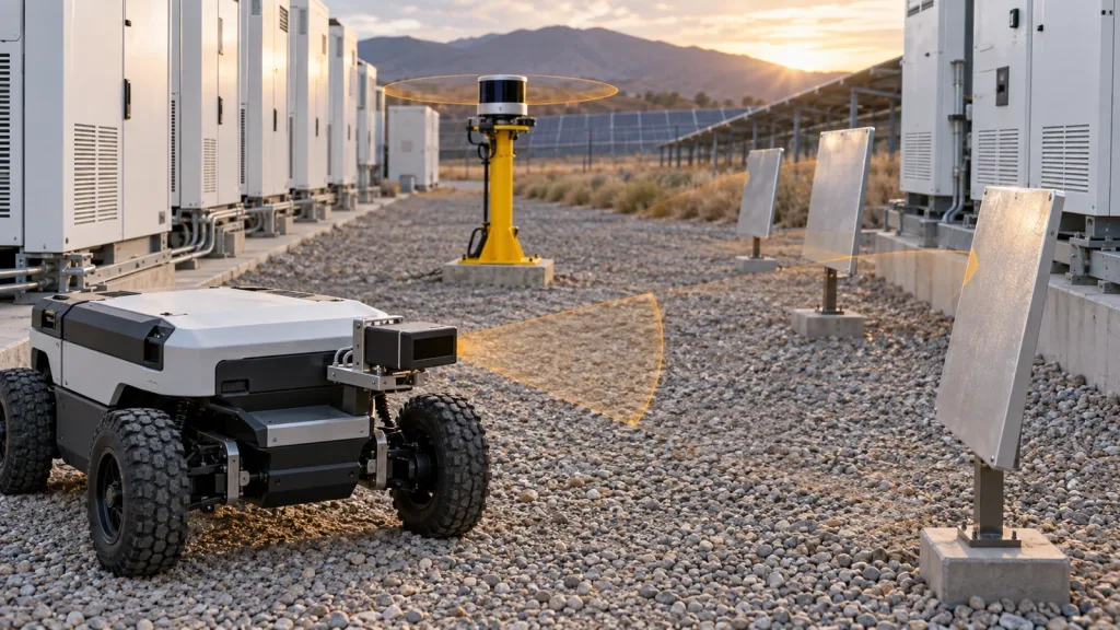
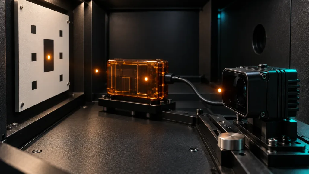
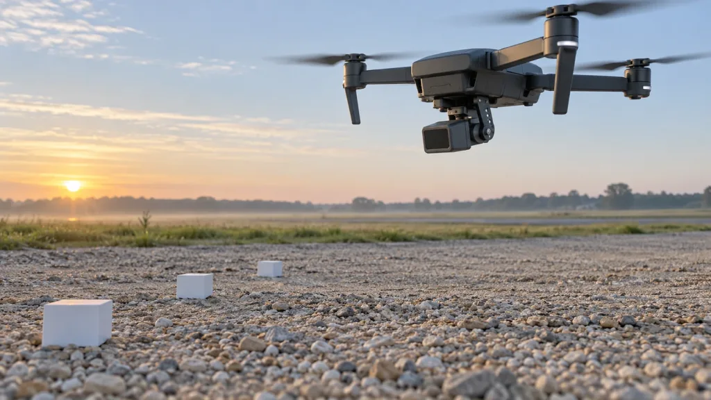
Build a modest, repeatable target set that represents the project’s real objects and required directions. Place low-profile calibration blocks across the predicted field-of-view edge at several mounting angles. Capture raw data before filtering, and retain a photo of the installed scene with each capture. The goal is not to claim a universal blind distance. It is to find where the current airframe, current bracket, current targets, and current scene cease to provide evidence the project can use.
3. Repeat the same card through changing conditions
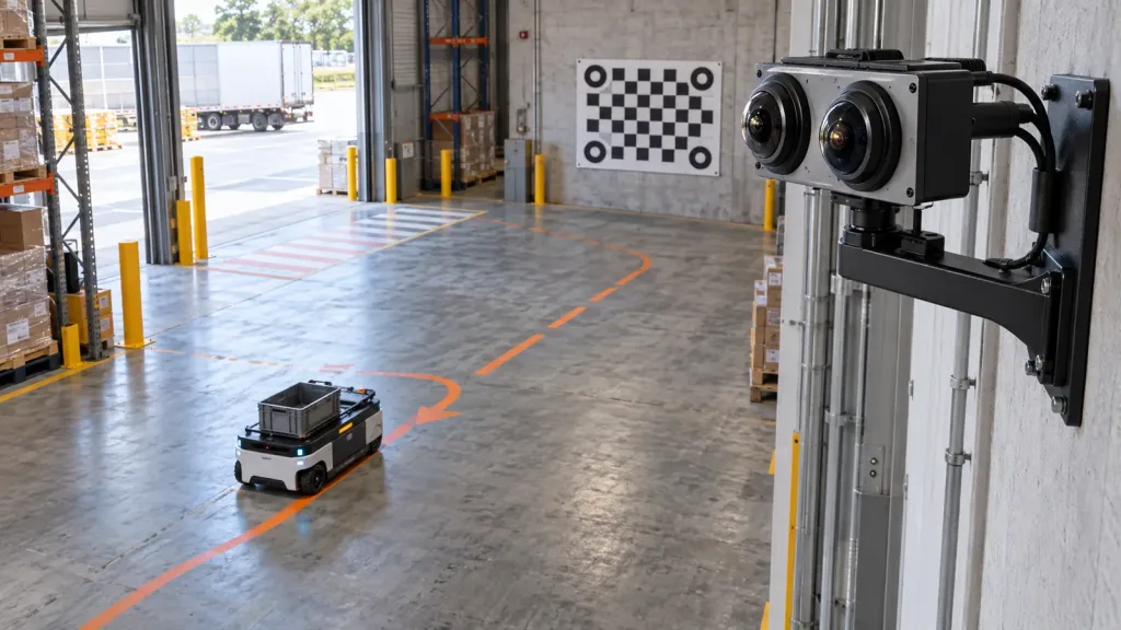
Run the identical target card after controlled changes in pitch, target angle, illumination, vibration state, window condition, and distance. Keep the project’s pass/fail rule in the sheet before viewing the output. A clean-looking depth image is not a pass criterion unless the team has already defined the data continuity, positional tolerance, and response boundary it needs.
4. Hand the tested data to the actual host
Only after the mount and raw capture are understood should the team check the chosen host path. The official ArduPilot rangefinder documentation describes rangefinder roles in supported configurations and explicitly notes that the configured maximum needs to be a tested, appropriate value. That is host-stack guidance, not evidence that this product is natively supported by ArduPilot. Confirm the actual sensor protocol, conversion layer, firmware, mode, and documentation for the build you are evaluating.
| Stage | Minimum evidence to save | Decision owner | Stop and review when |
|---|---|---|---|
| Mount sketch | Optical-centre position, bracket revision, aircraft outline, field-of-view rays, and occlusions | Mechanical + perception | The desired direction is blocked or the mount cannot be made repeatable. |
| Raw target capture | Scene photo, target description, distance, mount state, data file, and timestamp source | Perception | The required target cannot be distinguished consistently in the proposed envelope. |
| Repeatability check | Same test card under controlled scene changes and a declared acceptance rule | Systems test | A small installation or scene change reverses the result without a clear explanation. |
| Host handoff | Input mapping, source timing, logging, recovery procedure, and host-specific behavior record | Controls / integration | The project cannot state what the host receives, how old it is, or how it responds to absent data. |
Data and host-handoff questions before you choose UART, UVC, or UDP
The MRP-LD1 listing makes UART, UVC, and UDP available. That does not make one transport automatically right for a particular aircraft. Choose the interface by the evidence and recovery behavior the project needs—not by the shortest cable or the most familiar label. The site’s UART, UVC, or UDP interface guide can help frame the transport tradeoff, while the depth map versus point cloud guide helps distinguish the output a host must process.
- What exact protocol revision, sample data, field definitions, invalid-value rule, and timestamp semantics are available for the chosen transport?
- Does the recorded time describe sensor acquisition, host receipt, or later publication? Which clock owns it?
- How will the prototype preserve a raw example next to the post-processed output used by the host?
- What should happen after a cable, stream, packet, or host-process interruption, and how will recovery be demonstrated?
- Which transform connects the sensor optical frame to the aircraft frame, and who owns calibration after a bracket change?
Those questions intentionally do not assume a native driver, MAVLink message, ROS package, or autopilot feature. They make any needed conversion work visible early. Request the current manual, protocol material, SDK information, firmware details, and sample data through the site’s documentation resources before committing to a host architecture.
Illustrative case: compare three downward mount angles before a prototype flight
Illustrative planning scenario—not a customer result or MRP-LD1 performance claim: a compact quadcopter team is considering a downward-facing dToF module for a near-ground evaluation. Its three bracket positions are level, mildly downward, and more steeply downward. Rather than choose by appearance, the team draws all three field-of-view envelopes from the proposed optical centre and places the same low-profile blocks across each predicted lower edge.
For each mount state, the team saves the bracket revision, scene photo, target material and shape, distance, illumination condition, raw capture, decoded output, and any host-received record. A pitch that improves near-ground visibility may reduce upper-scene coverage or create more ground returns. The team therefore compares the three records against the same project-defined objective instead of promoting any angle as a universal answer.
When one mount has an acceptable physical and data record, the team moves to a restrained or otherwise controlled host test appropriate to its own safety process. It documents what the host receives and how it handles stale or unavailable source data. The output is a purchase and integration decision trail—not a promise that the aircraft will avoid every obstacle or maintain a particular altitude.
Common dToF module evaluation mistakes
- Using a maximum listed range as a mounting drawing. Range does not reveal aircraft occlusion, target angle, field-of-view boundary, or usable output in the installed scene.
- Checking only an uncluttered bench. A clear indoor view does not test the bracket, propeller plane, landing gear, target material, illumination, or motion context that matters later.
- Recording filtered output but not the raw capture. Without a raw reference, the team cannot separate an optical issue from a conversion or downstream filtering issue.
- Calling an interface a complete integration. UART, UVC, and UDP are listed interfaces; they are not evidence of a particular flight-controller driver or middleware path.
- Changing bracket geometry without updating the frame record. A revised pitch or optical-centre location changes the evidence the host should interpret.
- Using Class 1 as a system-level approval. The published module classification does not remove the aircraft project’s own risk, installation, and compliance responsibilities.
- Letting a supplier headline become the acceptance rule. Define the project target, scene, evidence, owner, and decision threshold before reviewing the capture.
RFQ and evaluation-sample checklist
An effective request tells the supplier what will be mounted, what will be measured, and which materials the engineering team needs to assess it. Include the following with an evaluation-sample request:
| Send or request | Why it belongs in the evaluation file |
|---|---|
| Aircraft outline, intended optical-centre location, pitch/yaw range, and bracket constraints | Allows a field-of-view fit conversation based on real geometry rather than generic directions. |
| Project targets, required directions, distances, materials, motion context, and scene conditions | Defines what “usable” means for this evaluation without turning a listing into a blanket promise. |
| Required output, host platform, selected transport, logging needs, and source-time expectation | Exposes data conversion and recovery work before an airframe integration date is fixed. |
| Current protocol, data-format, SDK, firmware, sample-data, and version information | Gives the team evidence to inspect instead of assuming a native software path. |
| Published specifications to compare | Lets the team align the planned test with the product’s listed range, field of view, output, rate, interfaces, power, and mass. |
| Acceptance card with owners, raw-capture location, and open questions | Creates a repeatable handoff between purchasing, mechanical, perception, and controls teams. |
The goal is not to make every uncertainty disappear before purchase. It is to name the uncertainties, collect the relevant evidence, and prevent an untested assumption from becoming a late-stage hardware or software surprise.
Start Your dToF Module Evaluation With the Right Inputs
Share your proposed UAV mount, required viewing directions, target conditions, host platform, preferred transport, and the raw data you need to retain. Purpleriver can help you compare those requirements with the MRP-LD1’s published parameters and prepare evaluation questions.