Obstacle avoidance is not proved when a UAV LiDAR module merely shows a plausible depth image on a bench. A multirotor team must prove the handoff from the sensor’s observed space to the vehicle’s directional decision: which directions are covered, how old the measurement is, what “unknown” means, and how the aircraft responds when that information is absent.
This guide is for an integration engineer or technical buyer evaluating a compact dToF module before a flight test. It separates the product’s published sensor facts from the host, message conversion, flight-controller configuration, and validation work that remain the aircraft team’s responsibility.
| Quick answer | Keep raw LiDAR evidence, mounting geometry, coordinate frame, data age, directional coverage, no-data behavior, and flight response in one test record. A range value without those links is not an obstacle-avoidance acceptance result. |
|---|---|
| Best fit | Compact multirotor programs that need to evaluate a depth module for short-range obstacle sensing before approving samples or flight tests. |
| Decision rule | Do not enable or market a complete avoidance function until the installed sensor, host conversion, vehicle margin, and degraded-data response have passed the project’s own controlled tests. |
Obstacle avoidance needs a directional data contract
A depth image, point cloud, rangefinder measurement, and flight-controller obstacle input are different things. The sensor observes a limited optical field; a host may transform, filter, aggregate, or reject that data; and the aircraft policy ultimately decides whether a command is allowed, slowed, or stopped. Each transition needs an explicit owner and a testable record.
Current PX4 collision-prevention documentation illustrates why this separation matters: its vehicle policy can use direct rangefinders or companion-computer data, constrains movement where data is unavailable by default, and specifies that its minimum distance is measured to the sensor rather than the outermost aircraft geometry. That is authoritative platform behavior, not a claim that any particular LiDAR module is natively supported or ready for a complete UAV safety function.
If you need the broader product context first, start with Purpleriver’s guide to what drone LiDAR means for UAV integration teams. This article focuses on the narrower, often-missed handoff that turns an installed sensor observation into directional flight evidence.
The LiDAR-to-vehicle handoff decision chart
| Handoff stage | What to record | Question to answer | Hold the test if |
|---|---|---|---|
| Raw observation | Device mode, raw depth/point evidence, confidence or invalid values, acquisition and host times | Did the installed sensor observe the representative obstacle? | The target disappears, is unlabeled, or cannot be related to a timestamp. |
| Installed geometry | Optical frame, measured mount transform, field-of-view sketch, propeller/chassis margin, self-occlusion photos | Which physical directions and obstacles can the sensor reasonably observe? | The drawing uses an assumed orientation or omits vehicle geometry. |
| Host conversion | Frame transform, units, filtering, angular bins or sectors, drop/restart rules, software versions | How did raw points become directional obstacle information? | A downstream range value cannot be traced back to source data. |
| Vehicle policy | Configured input, no-data rule, sensor-to-airframe margin, delay and response expectations | What does the aircraft do for covered, clear, stale, and unknown directions? | Unknown data is silently treated as clear without an approved policy. |
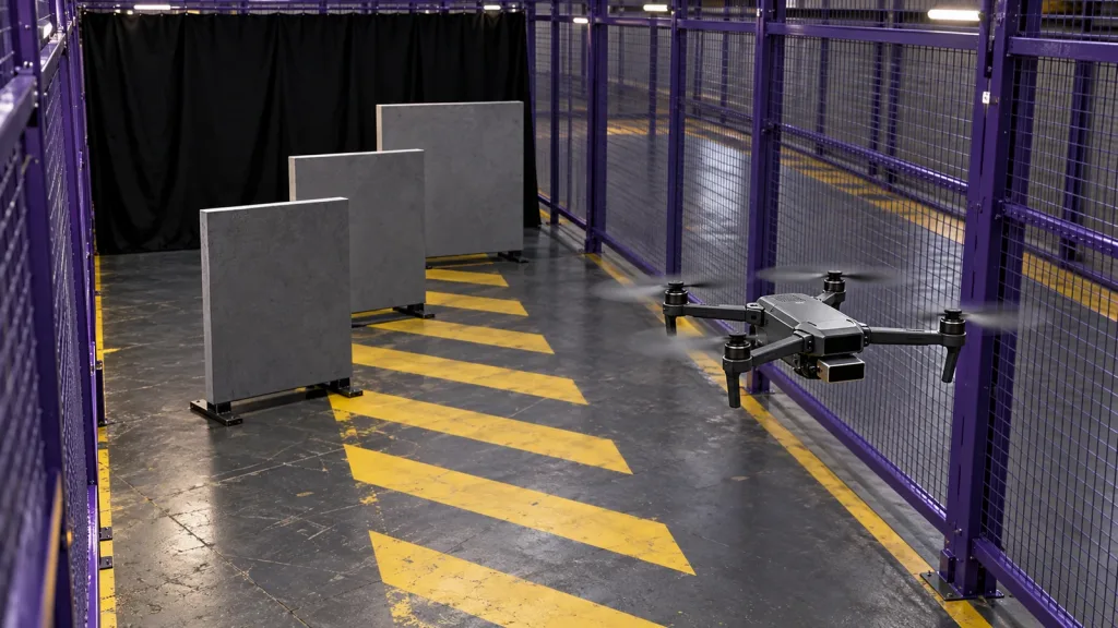
| Flight evidence | Controlled target runs, conditions, aircraft mode, operator procedure, logs, and pass criteria | Does the complete installed chain behave within the approved envelope? | The result depends on a single static bench capture. |
Published MRP-LD1 parameters to screen first
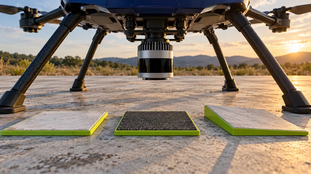
The current WooCommerce Featured product is the MRP-LD1 Drone LiDAR Sensor. Its listing identifies it as a solid-state SPAD dToF module that supplies depth images and 3D point-cloud data. It is not described as a complete obstacle-avoidance system: the host processor, perception logic, planning, flight controller, and validated response remain part of the full solution.
| Published parameter | MRP-LD1 value | Evaluation implication |
|---|---|---|
| Weight and power | 8 g; 1.2 W; 5 V supply | Measure the installed bracket, cable strain relief, and power behavior on the actual airframe rather than assuming a small module has no integration effect. |
| Ranging principle | SPAD dToF with 940 nm VCSEL | Plan to retain depth-oriented source evidence and verify the final installation in the intended scene. |
| Field of view and output | 60° horizontal × 45° vertical; 40 × 30 resolution; depth and point-cloud output | Draw the real coverage volume, including mounting angle and vehicle occlusion, before defining directional sectors. |
| Frame rate | 10 fps | Measure complete acquisition-to-decision age, jitter, filtering, and aircraft response; frame rate alone is not a safe reaction-distance claim. |
| Published range and ambient-light baseline | Indoor 0.5–25 m; outdoor 0.2–8 m; 80 Klux | Use representative target material, angle, glare, motion, and installed-window conditions in the project’s outdoor test plan. |
| Interfaces and platforms | UART, UVC, UDP; Windows, ARM, Linux, Android | Choose and document the actual host path. These facts do not by themselves establish a native autopilot driver or MAVLink output. |
For a direct range-and-condition planning example, use the site’s MRP-LD1 indoor/outdoor validation guide. For the difference between device interfaces, review UART, UVC, and UDP selection before committing host software.
Five evidence gates before a multirotor flight
- Freeze the physical drawing. Measure the optical center, axes, bracket tolerances, airframe silhouette, propeller margin, and intended field of view. Compare it with the body-frame method in this UAV alignment check.
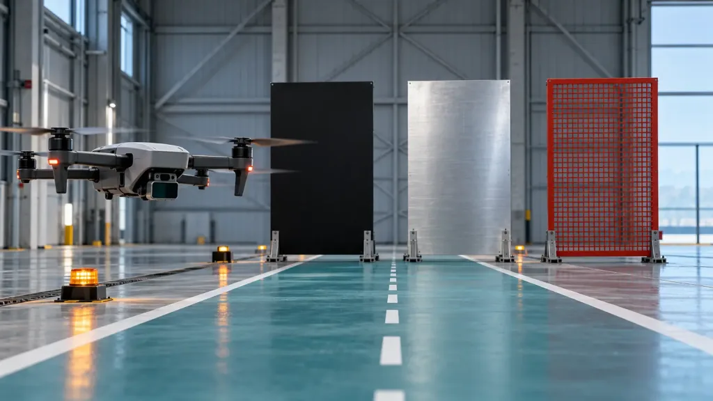
- Capture raw, representative observations. Use targets that represent the required material, size, angle, distance, ambient light, and motion. Save unfiltered captures before tuning a host filter. Include glare and reflectivity cases informed by the site’s sunlight and target-reflectivity guide.
- Make the conversion inspectable. Record every transform, unit conversion, point rejection rule, angular aggregation rule, and timestamp domain. A reviewer should be able to trace one directional obstacle report to a raw capture.
- Define clear, covered, stale, and unknown separately. “No obstacle observed” is not interchangeable with “no data available.” Decide the vehicle policy for each state, include sensor-to-airframe margin, and test a controlled stream interruption on the ground.
- Run a gated aircraft test. Start with a restrained or otherwise controlled setup approved by the responsible flight team. Add representative approach directions and speed only after the earlier evidence is accepted. Stop the test when coverage, time, or state labels are not trustworthy.
Interface, time, and direction semantics
If a companion computer or conversion layer sends directional obstacle data to a flight stack, its data contract must say how directions are ordered, which sensor frame applies, what timestamp is carried, and how invalid or out-of-range readings are represented. The official MAVLink OBSTACLE_DISTANCE definition describes obstacle distances across the sensor’s front from left to right in angular increments. That is a useful review checklist for a host converter; it does not mean the MRP-LD1 emits this message directly.
PX4’s current rangefinder documentation also treats physical setup and testing as part of distance-sensor use, including terrain, landing, and collision-prevention applications. Keep a strict boundary between platform documentation and the product record: confirm the actual driver, bridge, interface mode, and firmware with the flight-stack and sensor documentation available for your evaluation.
For each run, preserve the source timestamp, host reception time, transformed frame, distance units, sector/bin convention, validity rule, last-update age, and version identifiers. Do not convert a delayed or missing update into a fresh clear-space report. If the data path is unclear, request the relevant materials through the documentation resources page before planning a flight test.
Illustrative case: a steel-truss inspection approach
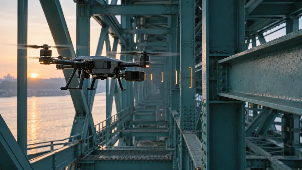
Illustrative engineering scenario, not a customer result: a team is evaluating a compact multirotor for a slow, supervised approach beneath a steel-truss structure. The aircraft carries a forward-looking compact dToF module. Its project requirement is not “detect every obstacle”; it is to provide a documented, directional observation to the host for the particular crossbeam approach envelope chosen by the flight team.
The team first photographs the final mount and draws the sensor optical frame against the airframe and crossbeam. It records raw depth or cloud data with target locations, then applies a documented transform and directional aggregation step. Every report carries an acquisition-time/host-time record and a state: covered-clear, covered-obstacle, invalid, or stale/unknown.
On the ground, the team removes the input stream to confirm that the host and vehicle path handle stale data as specified. In a controlled flight evaluation, it uses the same crossbeam geometry at documented approach directions and conditions. The acceptance artifact links each vehicle response to the raw source and software version. The result is evidence for that bounded configuration—not a general performance promise or a substitute for the project’s flight-safety process.
Common obstacle-avoidance handoff mistakes
- Equating a sensor’s maximum range with aircraft clearance. Vehicle geometry, coverage, delay, state policy, and response still matter.
- Measuring to the enclosure rather than the optical frame. The transform must represent the actual sensing origin and orientation.
- Using a bench depth image as a flight acceptance result. It cannot prove directional mapping, data age, aircraft margin, or the degraded-data response.
- Making unknown look clear. Missing coverage, invalid data, and a stale stream require an explicit, tested behavior.
- Claiming native platform support from a listed interface. UART, UVC, or UDP does not prove a specific flight-controller driver or message bridge.
- Filtering before retaining raw evidence. A clean downstream signal can hide whether a target was never observed or discarded later.
- Testing only one reflectivity or light condition. Include the intended target material, angle, installed window, glare, and motion cases.
- Calling a perception feature a complete safety system. Keep product facts, aircraft integration, operational procedure, and formal safety work distinct.
RFQ and evaluation-sample checklist
Ask for the facts needed to build the above chain, rather than only asking for a headline range. Share:
- airframe type, intended obstacle directions, proposed sensor location/orientation, vehicle envelope, and available mounting volume;
- the smallest representative target, material, angle, working distances, target movement, sunlight/glare conditions, and installed-window constraints;
- the required depth or point output, invalid/confidence behavior, timestamp expectations, coordinate convention, and sample-data needs;
- the selected UART, UVC, or UDP path, host operating system, software version, logging needs, restart behavior, and expected conversion responsibility;
- the vehicle policy for covered-clear, covered-obstacle, invalid, stale, and unknown directions, including the aircraft-margin owner;
- test gates, evidence format, project-defined pass criteria, and the change-control record needed before any new flight trial; and
- the project schedule, sample quantity, and technical questions to resolve without assuming price, stock, delivery, or unlisted product behavior.
Turn your sensor question into an evaluation record
Share the target aircraft, direction of interest, mounting sketch, working range, light conditions, host platform, preferred interface, and the evidence you need. Purpleriver can help you compare those requirements with the MRP-LD1’s published parameters and identify the documentation questions for an evaluation sample.