Integration & SDK
Drone LiDAR Resources: Build a First Bench Evidence Pack
A compact LiDAR module on a UAV frame is not yet an obstacle-avoidance function. Before a team asks a flight-control engineer to act on a measurement, it needs a small, traceable evidence pack: what the sensor is documented to output, how the host received it, what scene produced it, and which questions remain open. These drone LiDAR resources turn a first bench session into a useful engineering handoff instead of a collection of screenshots.
Quick answer
Start with six items: the exact product fact sheet, an interface and power note, one raw capture, a scene-and-target log, a mounting/orientation sketch, and a written handoff question for the host and flight-control teams. Do this without propellers first. It makes it possible to decide whether the next task is data parsing, mounting validation, perception logic, or a controlled system test.
Drone LiDAR resources should produce evidence, not just bookmarks
A useful resource has a job. A product page confirms what may be evaluated; an interface document tells the host developer what must be decoded; a captured frame exposes whether the data path works; and a test note prevents a later reviewer from guessing what the sensor was facing. The table below is a practical sorting rule for a first integration session.
| Resource | Evidence to keep | Decision it supports | Do not infer |
|---|---|---|---|
| Featured-product facts | Parameter table and product URL | Whether the documented form factor, outputs, interfaces, and baseline fit the evaluation scope | Flight-controller compatibility or a complete avoidance function |
| Interface note | Power, common-ground, cable, host, and selected-interface record | Who owns the parser and where data becomes available | That a connector alone establishes a control path |
| Raw or rendered sample | Original capture plus the tool/version used to view it | Whether the host is receiving interpretable depth or point-cloud output | Range, accuracy, or safety in every operating condition |
| Scene log | Target material, angle, distance, ambient condition, mount position, and motion state | What a result actually represents and what to repeat | That an unrecorded demo is reproducible |
| Data-handoff contract | Timestamp, frame/orientation, validity, uncertainty/quality, and consumer behavior | Whether a companion computer and flight stack have a shared question | Native protocol support by a sensor not documented for that protocol |
For example, the official MAVLink DISTANCE_SENSOR definition is a useful review model when a project uses MAVLink: it makes timestamp, valid distance limits, orientation, field of view, and signal-quality semantics explicit. It is not evidence that any particular sensor natively speaks MAVLink.
Keep the product facts separate from the system promise
For an early embedded evaluation, the available Featured product is the MRP-LD1 Drone LiDAR Sensor. The values below are documented product facts to place in the evidence pack. They are screening inputs, not a substitute for testing the intended scene.
| Documented item | MRP-LD1 value | Bench-session use |
|---|---|---|
| Architecture | Solid-state SPAD dToF LiDAR with 940 nm VCSEL | Record the sensing approach alongside the host's evaluation assumptions |
| Weight and power consumption | 8 g; 1.2 W | Start a payload and power-budget discussion; verify the complete installation separately |
| Documented ranging baselines | 0.5–25 m indoors; 0.2–8 m outdoors | Choose initial target positions, then validate the intended target, angle, light, mount, and motion |
| Field of view and resolution | 60° (H) × 45° (V); 40 × 30 | Draw the mounted field of view before deciding which sector is represented |
| Frame rate | 10 fps | Log the delivered cadence observed by the host rather than assuming an end-to-end control response |
| Outputs and interfaces | Depth images and 3D point-cloud data; UART, UVC, UDP | Choose one first data path and preserve a sample |
| Listed software support | Windows, ARM, Linux, Android | Record the actual host environment and version used during the evaluation |
MRP-LD1 supplies depth images and 3D point-cloud data; the host processor, perception logic, planning, flight controller, and validated response remain parts of a complete system. That boundary is the reason an evidence pack is valuable.
A first bench workflow that another engineer can repeat
1. State one sensing question
Write a narrow question such as: “Can the selected host receive a recorded depth output from a fixed target at this mounted orientation?” Do not start with “Will the drone avoid obstacles?” The narrow question creates a result that can be verified without conflating sensing, planning, and flight behavior.
2. Freeze the documented baseline
Save the product link, the selected interface, the host operating system, the power arrangement, and a sketch of the sensor's physical orientation. Review the site's UART, UVC, and UDP interface guide before treating an output format as interchangeable.
3. Capture one reproducible sample
Keep the original file or packet capture, then make a separate viewing copy. A rendered point cloud can help a teammate inspect structure, but the raw capture, capture time, host, and parser version make the observation traceable. The depth-data visualisation guide is a useful companion for this step.
4. Log the scene before changing it
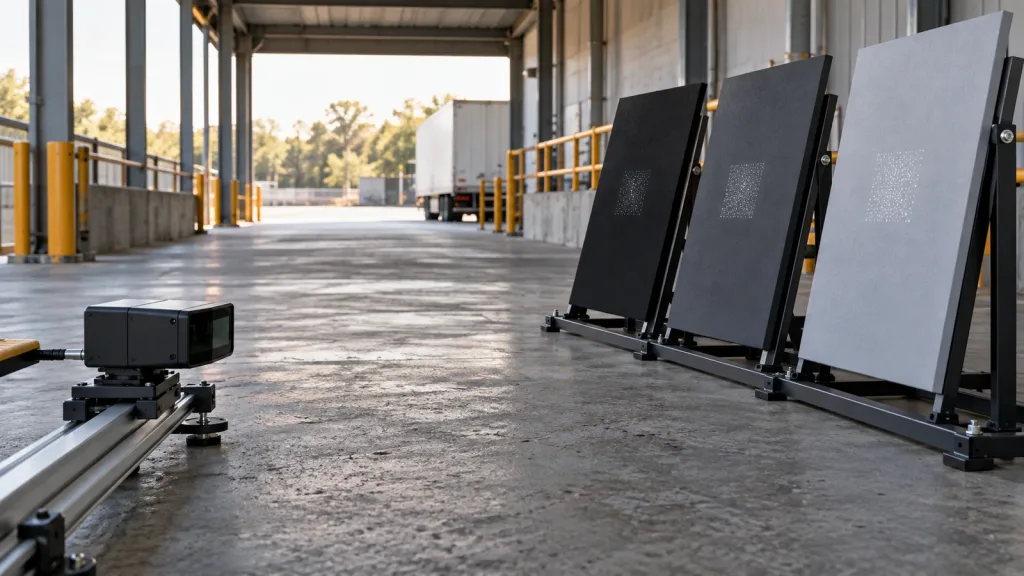
Record the target material and geometry, distance, relative angle, ambient condition, whether the airframe was static, and the mounting orientation. This is not bureaucracy: SPAD dToF ranging research examines how factors such as detector dead time, photon flux, pulse width, and time quantisation can affect ranging precision. Read the primary dToF ranging study as a reason to preserve conditions, not as a prediction for this module or this aircraft.
5. End with an owned handoff question
Examples: “Which process validates packet length and unit semantics?” “Who transforms the measurement into the vehicle frame?” “What does the consumer do with stale or invalid data?” The next owner can answer a precise question instead of reverse-engineering a demo. For a deeper template, see the LiDAR data-contract and flight-controller handoff guide.
Define the interface and data handoff before any flight assumption
Choose UART, UVC, or UDP for the first evaluation path according to what the host can observe and archive cleanly. Then write a small contract with six headings: source, clock/timestamp, coordinate or mounting frame, valid-data condition, quality/uncertainty semantics, and the consumer's response to missing or stale data. If the project later uses an autopilot or middleware protocol, verify that integration against the exact controller and software versions. The current PX4 obstacle-avoidance documentation is one independent starting point for reviewing a flight-stack path; it does not prove product compatibility.
Use the troubleshooting guide on common LiDAR integration issues when the first task is simply to establish an observable, repeatable data path. Keep that diagnosis separate from any flight test decision.
Realistic case: a utility-inspection prototype needs a clean handoff
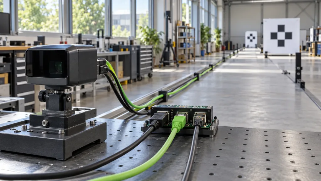
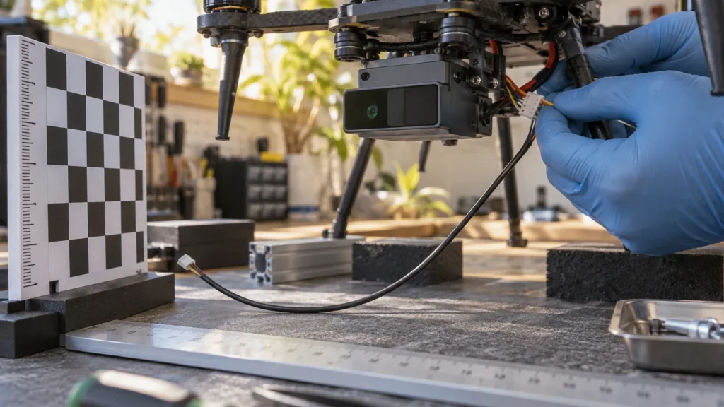
Imagine a small UAV team exploring a forward-looking sensing aid for a utility-inspection prototype. The initial aim is not autonomous flight. On a secured, unpowered bench, the team mounts the module in the intended position, selects one host interface, and captures a fixed-target sample. The evidence pack contains the mount sketch, product fact table, raw sample, scene log, and a question for the companion-computer owner: how are valid readings timestamped and transformed before another component consumes them?
That package exposes productive next work. If the host cannot parse the sample, solve the data path. If the mount places the target outside the documented field of view, revise the mechanical question. If the output is available but the control consumer is undefined, plan a software-interface review. None of those results claims that the aircraft can safely avoid an obstacle; each reduces uncertainty before a controlled system-level validation is considered.
Common mistakes that weaken the first evidence pack
- Calling a sensor demo an avoidance demo. A depth frame is not perception, planning, controller integration, or validated response.
- Keeping only a screenshot. Preserve the raw sample and the viewing/parsing context so another engineer can reproduce the result.
- Leaving orientation implicit. “Forward” has no shared meaning until the sensor mount and vehicle frame are recorded.
- Changing target, distance, and light together. The resulting capture cannot tell the next reviewer which condition changed the observation.
- Assuming a named protocol. A standard can be a useful contract template, but compatibility must be documented and tested for the exact stack.
- Taking the first powered test directly to flight. Work through bench evidence and system-level validation under the project's applicable safety and operating procedures.
RFQ and evaluation checklist
Before requesting an evaluation sample, project-specific quote, documents, or support, send a concise technical brief:
- Target platform and physical mounting location
- Application and the first narrow sensing question
- Working-distance range and whether the first evaluation is indoor or outdoor
- Host system, operating environment, and preferred interface
- Target material/scene conditions planned for the first capture
- Data form required by the host and the owner of parsing/integration
- Sample quantity and expected project timing
- The evidence you will return after the bench session and the open handoff question
Turn the first capture into a useful evaluation request
Share your platform, working distance, scene, host system, preferred interface, and the evidence question you need answered. Purpleriver can provide product documents, SDK resources, sample data, an evaluation sample, or a project-specific quote for the documented MRP-LD1 evaluation path.