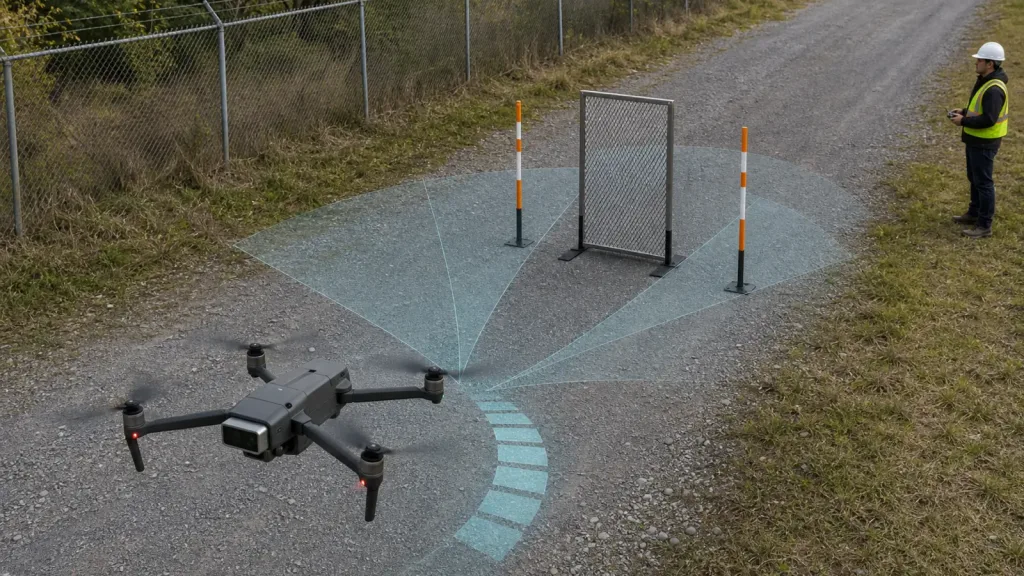
Drones obstacle avoidance only becomes credible when a UAV team can prove where the sensor sees well, where it does not, and how the aircraft reacts before contact. The engineering problem is not whether a compact LiDAR module can return distance on a bench. It is whether the aircraft can slow inside a believable brake window, survive blind-sector edge cases, and hand control back cleanly when the route exceeds the sensor setup that was actually tested.
This guide is written for UAV integration engineers and technical buyers who need a practical validation workflow before they approve a compact dToF module for guarded obstacle-avoidance routes, low-altitude inspection work, or pilot deployments.
| Quick answer | Validate drones obstacle avoidance by proving sector coverage, thin-obstacle detection, usable brake margin, controller slowdown or stop behavior, and a replayable data path before the aircraft enters a real pilot route. |
|---|---|
| Best fit | UAV teams evaluating a compact LiDAR module for near-field route protection, guarded slowdown, or first-stage obstacle-awareness programs. |
| Decision rule | If the team cannot explain what the module covers, what it misses, and what the flight stack does at the limit of that coverage, the setup is not ready to be called obstacle avoidance in the field. |
Drones obstacle avoidance validation starts with sector coverage, not marketing claims
Official flight-stack documentation already points toward the right mindset. ArduPilot documents simple object avoidance as a behavior that depends on proximity sensors or supported rangefinders, and its rangefinder overview warns that these features should be used with caution. PX4 describes collision prevention as a workflow that can automatically slow and stop a multicopter before it crashes into an obstacle, but only in supported vehicle and mode combinations. Those are system statements, not product guarantees.
That means a compact LiDAR module should be validated as part of an aircraft behavior chain, not as a stand-alone component demo. The team needs to know five things before trusting it in a route: the view sector it really covers after mounting, the obstacle types that stay reliable inside that sector, the brake distance that remains believable at the intended speed, the controller response when the obstacle enters that window, and the evidence path that lets weak runs be replayed instead of argued about afterward.
If you need the broader background first, Purpleriver already covers what drone LiDAR means for UAV integration teams and the site's higher-level real-world obstacle-avoidance requirements. This article starts later in the workflow: proving that a compact sensor installation can support a guarded route without overstating what one module can do.
Decision matrix for obstacle-avoidance proof
| Evaluation area | What to verify | Why it matters | Reject if |
|---|---|---|---|
| Sector coverage | What part of the route remains inside the mounted sensor view during hover, pitch change, and braking | Avoidance fails at the sector edge before it fails at maximum range | No one can draw the practical coverage zone after mounting |
| Obstacle class | Rigid panel, fence post, mesh, foliage edge, and partial side intrusion checks | Obstacle-avoidance credibility depends on what was actually tested, not on one big target | The validation set contains only one easy flat obstacle |
| Brake margin | Aircraft speed, detection distance, and slowdown or stop response on the intended route | A valid sensing window must still leave usable reaction distance | The aircraft reaches the obstacle before the team can show controlled deceleration |
| Controller handoff | Mode behavior when the sensor loses coverage, sees only partial returns, or leaves the intended route geometry | Weak or changing returns are normal edge cases in outdoor pilot work | The team treats controller intervention as a black box |
| Evidence path | Synchronized sensor output, route markers, and flight-log events for replay | Weak runs must be diagnosable after the flight | The team cannot align the sensor event with the aircraft response |
Exact featured-product parameters to validate
The current Featured product for this workflow is the LiDAR Drone Module - MRP-LD1 Solid-State dToF Sensor. The export explicitly lists UAV obstacle avoidance and altitude hold among the supported application scopes, so it is the correct factual product basis for this article.
| Parameter | Published value | Obstacle-avoidance implication |
|---|---|---|
| Ranging principle | dTOF | Use timing-aware logging and route replay instead of treating the module like a simple yes or no trigger. |
| Scanning principle | SPAD | Validate scene performance in real route geometry rather than assuming one reflector predicts all obstacles. |
| Emitter | 940nm VCSEL | Daylight route checks and mixed-surface conditions belong in the acceptance plan. |
| Laser safety | Class 1 | Useful for system screening, but not a substitute for proving route behavior. |
| Range | Indoor 0.5-25m; outdoor 0.2-8m | For obstacle avoidance, validate the outdoor brake window, not the headline indoor maximum. |
| Ambient-light resistance | 80Klux | Bright-sky and reflective-ground segments must be part of the route plan if the drone flies outside. |
| Accuracy | 0.2-1m <= +/-3cm; 1-5m <= +/-5cm; 5-8m <= +/-10cm; 8-15m <= +/-20cm | Translate each band into detection confidence and deceleration margin for the intended speed. |
| FoV | 60 degrees (H) x 45 degrees (V) | Check whether pitch angle, mount offset, or landing gear remove the part of the scene that matters most. |
| Resolution / frame rate | 40 x 30 at 10fps | Useful for many guarded UAV checks if the route and speed stay matched to the available sensing detail. |
| Interfaces | UART / UVC / UDP | Pick the path that gives the fastest repeatable logs before optimizing the final system architecture. |
| Software support | Windows / ARM / Linux / Android | Helpful when the bench logger, companion computer, and field laptop are not the same host. |
| Power / weight | 5V, 1.2W, 8g | Favorable for compact UAV payload budgets, but cable routing and mount stiffness still need proof. |
Bench-to-route workflow before pilot approval
1. Define the protected route and speed before the first flight
Obstacle avoidance is route-dependent. Write down the protected segment, the expected aircraft speed, and the kind of obstacle that matters. A slow inspection quadrotor moving through a fenced service lane is a different problem from a fast open-area crossing. Without a route definition, no brake margin is meaningful.
2. Draw the mounted coverage wedge, then test its edges
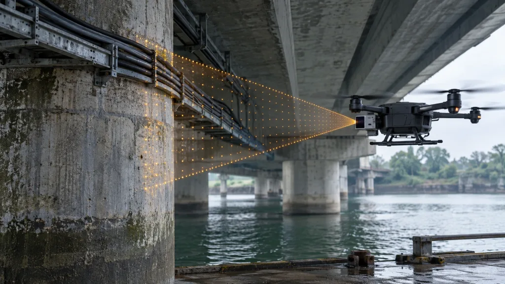
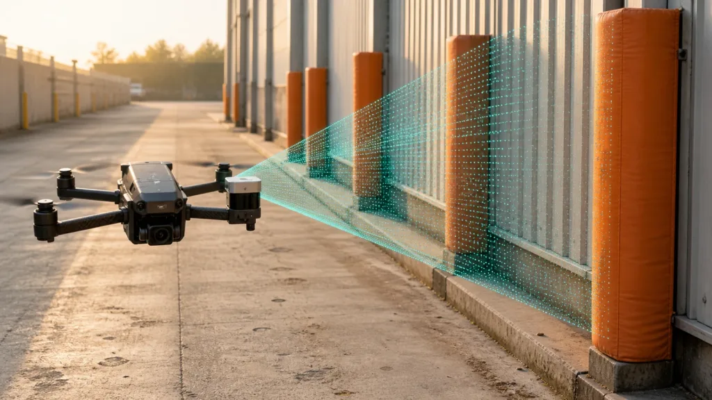
The MRP-LD1 data sheet gives a 60 degrees by 45 degrees field of view. That is only the start. After mounting, map what part of the route stays inside view during small pitch changes, bank, and deceleration. The first meaningful obstacle test should happen at the sector edge, because that is where route protection usually becomes ambiguous.
3. Use more than one obstacle class in the first guarded run
Large flat targets are not enough. Include at least one rigid board or panel, one narrow vertical feature such as a pole or marker, and one partial or textured edge such as fence mesh or brush line. The goal is not to promise universal sensing. It is to learn where the installed system remains believable and where it becomes a caution zone.
4. Prove slowdown and stop margin, not just detection
PX4's collision-prevention guidance and ArduPilot's avoidance documentation are both useful only if the aircraft still has room to react after the obstacle is sensed. Measure the route speed, detection point, and vehicle response on each pass. A good detection screenshot with no believable stop margin is not an approval result.
5. Force controller edge cases before expanding the route
Run controlled passes where the obstacle enters at the sector edge, where the aircraft yaws slightly off-axis, and where the sensor must deal with uneven ground underneath the route. That last case matters because obstacle routes often happen at low altitude, where route geometry and distance-sensor behavior overlap. If the team cannot explain the controller response in those cases, the setup is not ready for broader field work.
Interface, data, and controller handoff planning
Compact avoidance setups usually fail at the handoff layer before they fail in optics. The table below is meant to keep the LiDAR, embedded, and flight-controls owners aligned before they tune the wrong thing.
| Integration topic | Questions to answer |
|---|---|
| Mounting geometry | Does the sensor keep the route's critical obstacle sector in view during pitch and braking? |
| Interface choice | Which first-stage path produces synchronized evidence fastest: UART, UVC, or UDP? |
| Controller consumption | Will the flight stack read a direct distance feed, companion-computer output, or a filtered guard signal? |
| Intervention logic | What exactly should the aircraft do when the obstacle enters the brake window: slow, stop, or refuse further approach? |
| Edge-case logging | Can the team replay sector-edge misses, late stops, and partial detections after the run? |
| Support workflow | Which host platform will be used for bench capture and field debugging: Windows, ARM, Linux, or Android? |
For follow-up debugging, the most relevant internal references are Purpleriver's guide on UART, UVC, or UDP, the article on common LiDAR integration issues, and the documentation hub. Those resources help the team separate route-geometry problems from interface or parser failures.
Realistic application case: a fenced service lane with narrow obstacles and short stopping distance
Consider a compact quadrotor inspecting a low-altitude gravel service lane next to a chain-link fence and brush line. The program goal is not full autonomy. It is guarded approach behavior that slows the aircraft before it reaches posts, mesh edges, or route intrusions during short inspection runs.
- Bench-log the module against a large panel, a slim pole, and a partial mesh obstacle at distances that match the intended route speed.
- Mount the sensor in its real airframe position and verify that the nose, landing gear, and braking attitude do not hide the useful sector.
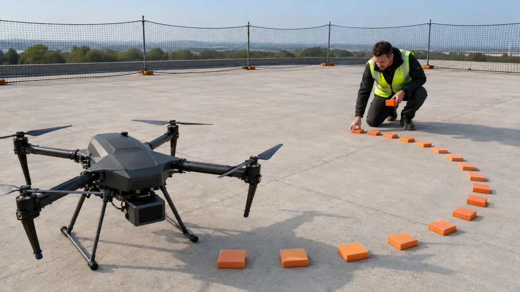
- Mark a route with visible stop lines so the team can compare detection distance to the actual remaining brake window.
- Fly guarded passes with small yaw offsets and slight height changes to expose sector-edge ambiguity instead of only centered obstacles.
- Replay the sensor output and controller response together to decide whether the system is ready for more route complexity.
This workflow is useful because it tests the real buyer question: whether one compact module can support a believable first-stage avoidance behavior on a defined route without pretending to deliver omnidirectional protection it was never validated to provide.
Common mistakes when validating drones obstacle avoidance
- Using maximum range as the acceptance rule instead of proving usable brake distance at the real route speed.
- Testing only one large flat target and calling the result obstacle avoidance.
- Ignoring how pitch angle or airframe hardware changes the practical coverage wedge.
- Assuming a centered front approach proves what happens at sector edges or during slight yaw offsets.
- Logging only pass or fail outcomes instead of synchronized sensor and controller evidence.
- Overstating a forward or partial-sector installation as omnidirectional protection.
RFQ and engineering checklist
| Checklist item | Why it belongs in the validation sheet |
|---|---|
| Protected route definition | Sets the speed, obstacle class, and geometry the module is expected to support. |
| Mounted coverage sketch | Prevents teams from confusing optical FoV with route-relevant coverage. |
| Obstacle set | Forces testing of rigid, narrow, and partial targets instead of one easy board. |
| Brake-margin threshold | Turns detection distance into a real pilot-route decision. |
| Controller intervention rule | Clarifies whether the aircraft should slow, stop, or reject further approach. |
| Route-edge test plan | Exposes blind-sector and off-axis cases before deployment. |
| Replay workflow | Makes weak runs explainable after the flight. |
| Vendor support packet | Helps the next discussion start with route geometry, speed, and observed edge cases. |
When a compact dToF module is ready for the next guarded route
If your team can already define the protected route, draw the mounted coverage wedge, show usable brake margin, and replay controller intervention against real obstacle classes, a compact module can move into the next pilot stage with much less guesswork. If those items are still vague, tighten the validation sheet before expanding the route.
Purpleriver's featured MRP-LD1 solid-state dToF sensor is relevant for teams evaluating UAV obstacle avoidance, altitude hold, and compact route-awareness workflows. To discuss fit with your own airframe, use the contact page and include the intended route geometry, speed, mount angle, controller stack, and logging method.