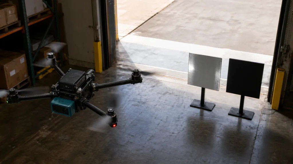
Forward Obstacle Sensing is only useful on a drone when the front sensor can prove three things at the same time: it sees the obstacle geometry that matters, it leaves enough stopping margin for the aircraft, and the autopilot can turn that measurement into a real flight action instead of a late warning. Teams usually fail when they test the sensor as a component and never validate the full stop-or-slow workflow.
This guide is for UAV integration teams and technical buyers who need a practical validation path before approving close-approach flight tests. The goal is not to claim that any single front-facing LiDAR solves every avoidance problem. The goal is to show what evidence turns Forward Obstacle Sensing from a promising demo into a trustworthy flight behavior.
| Quick answer | Approve forward obstacle sensing only after you validate front-sector coverage, obstacle-to-stop-distance margin, reflective-target behavior, and the exact autopilot data handoff that will slow or stop the aircraft before contact. |
|---|---|
| Best fit | Compact UAV programs that need bounded front-facing awareness for doorway checks, rooftop service-lane passes, low-altitude inspection approaches, or cautious obstacle-stop workflows. |
| Decision rule | If the team cannot explain which obstacle sectors are covered, how much stopping distance remains at approach speed, and how the sensor output becomes a control decision, the system is not flight-ready. |
Why forward obstacle sensing fails in real UAV tests
Most front-sensor failures are not caused by a missing spec-sheet number. They happen because the drone team never writes down the obstacle volume and stopping behavior the aircraft actually needs. A narrow pole, railing edge, doorway frame, suspended cable, or reflective cabinet corner can all behave differently from the flat target that looked easy on the bench. That is why the first question is not "does the module detect something in front?" It is "does it detect the exact front hazard early enough for this aircraft to change behavior safely?"
The Reddit question set behind this topic reinforces that point. Users were asking why obstacle avoidance failed in open space, whether lidar or front sensors really help when false alarms happen, and how much sensing is actually needed before a vehicle can trust the stop logic. Those are planning questions, not proof. The technical proof comes from current autopilot documentation and your own test workflow.
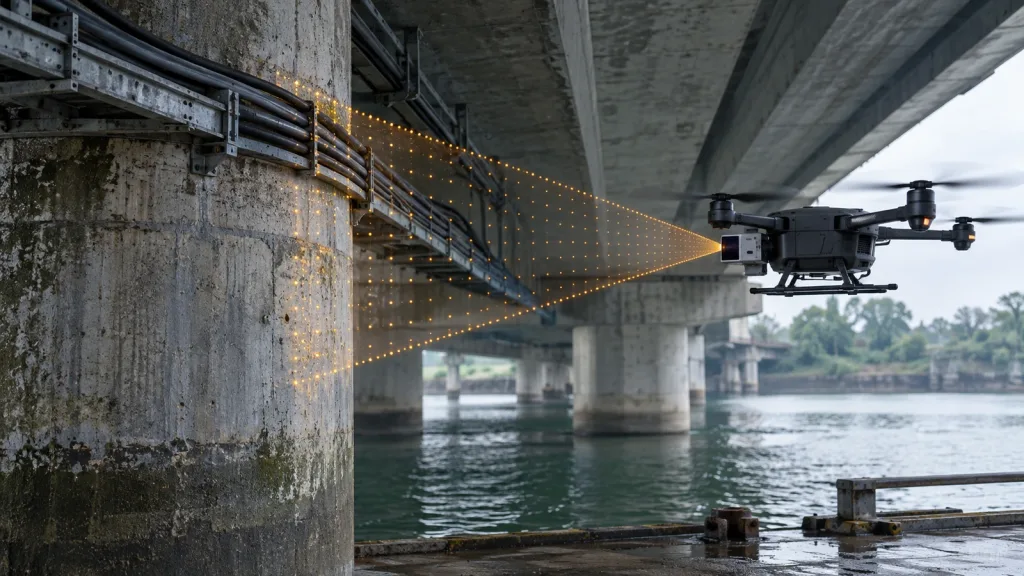
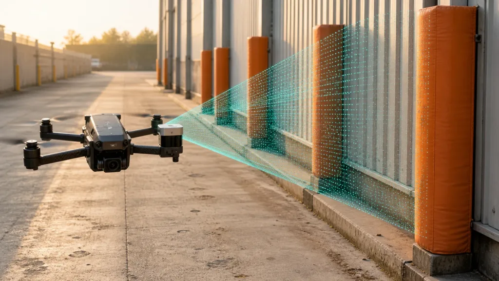
PX4's current rangefinder guidance makes the system-level role explicit: distance sensors are used for terrain following, terrain holding, improved landing behavior, and collision prevention. Its collision-prevention documentation goes further by describing an internal obstacle map split into 72 sectors around the vehicle. That means a front sensor is not judged only by raw distance output. It is judged by whether the obstacle data reaching the flight stack covers the directions the vehicle may move into.
ArduPilot's current documentation points to the same discipline from another angle. It separates narrow-ray rangefinders from wider proximity sensing and explains that object avoidance can use either a 360-degree lidar or multiple directional sensors. In practice, that means drone obstacle-avoidance requirements should be mapped as sectors and blind zones, not just as a single advertised range number.
Forward obstacle sensing validation matrix
| Validation question | Why it matters | Pass signal | Red flag |
|---|---|---|---|
| Does the front coverage match the hazard geometry? | The aircraft only benefits if rails, doorway edges, pipes, and narrow posts fall inside the usable sensing sectors. | The team maps obstacle visibility against stand-off distance and approach angle. | The review stops at one FoV number with no target layout. |
| Is stopping distance larger than detection-to-action delay? | A front sensor is worthless if the drone is still moving too fast when the control stack reacts. | The test plan ties approach speed, sensor update, and stop margin into one acceptance rule. | There is no defined distance at which the aircraft must slow or stop. |
| How does the system behave on reflective and low-contrast targets? | Mixed target materials often trigger either missed detections or unnecessary slow-downs. | The team compares matte and reflective targets in the same scene. | The demo uses only one easy wall target. |
| Can the autopilot consume the front data in the intended mode? | The useful system is the handoff into obstacle sectors or proximity logic, not the sensor stream by itself. | The team can show the exact transport, parsing, and flight-stack destination for the data. | The workflow depends on undefined middleware or "future integration." |
| Are blind zones understood and acceptable? | Any uncovered region becomes a real operational assumption. | The test record documents the allowed blind zones and the flight behavior that compensates for them. | The team assumes "front-facing" means full front protection. |
Exact featured-product reference parameters
The featured Purpleriver module below is used only as a factual reference point for a front-sensing workflow. It does not prove fitness by itself. It defines the packaging, range, field-of-view, and interface baseline that a UAV team can validate against the mission it actually cares about.
| Product | LiDAR Drone Module – MRP-LD1 Solid-State dToF Sensor |
|---|---|
| Ranging principle | dTOF (Direct Time-of-Flight) |
| Scanning principle | SPAD |
| Emitter | 940nm VCSEL |
| Laser safety | Class 1 (FDA Recognized Eye-Safe) |
| Range | Indoor 0.5-25m; outdoor 0.2-8m |
| Ambient-light resistance | 80Klux |
| Accuracy | 0.2-1m <= +/-3cm; 1-5m <= +/-5cm; 5-8m <= +/-10cm; 8-15m <= +/-20cm |
| Field of view | 60 degrees (H) x 45 degrees (V) |
| Resolution / frame rate | 40 x 30 at 10fps |
| Interfaces | UART / UVC / UDP |
| Software support | Windows / ARM / Linux / Android |
| Power / weight | 5V, 1.2W, 8g |
Those numbers matter because they shape the real UAV trade-off. A front-sensing workflow that needs more stand-off distance, wider coverage, or a different data path must prove why this compact baseline is insufficient. If the workflow fits inside this envelope, the validation burden shifts to scene geometry and control behavior rather than to headline specs alone.
Validation workflow before field approval
- Define the exact stop or slow-down rule. Write down the approach speed, minimum warning distance, and flight behavior the sensor must trigger.
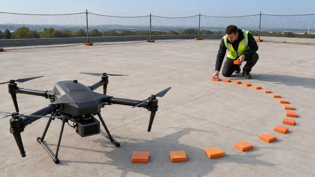
- Build a front-sector test lane using at least one narrow target, one reflective target, and one broad flat obstacle. Test them at the angles and distances the mission actually uses.
- Mark the decision distance on the floor or in the test area. If the system recognizes the obstacle only after that line, the workflow has not passed even if the sensor eventually reports a distance.
- Repeat the same approach under the ambient light and target contrast conditions the aircraft will really face, especially for doorway, loading-bay, rooftop, or utility-corridor work.
- Replay the data through the intended host path, whether that is UART, UVC, or UDP, and verify the autopilot sees usable front-sector information rather than a disconnected sensor stream.
- Document the blind zones that remain and define the pilot or autonomy constraint that compensates for them.
This is the practical difference between a sensor demo and a flight workflow. A "works in front" clip is not enough. The system passes only when the stop-distance rule, target coverage, and handoff behavior all survive the same test lane. If you are still early in the program, review what drone LiDAR means for UAV integration teams before you lock the acceptance plan.
Interface, sectors, and autopilot handoff
The integration step is where most front-sensor projects become ambiguous. PX4 states that distance sensors can serve terrain following, terrain holding, improved landing behavior, and collision prevention, and that front-facing sensors writing to ObstacleDistance can be used to test collision-prevention flows. Its collision-prevention guide describes a 72-sector internal obstacle map. That is a concrete reminder that a front sensor is judged by sector coverage and freshness, not by distance numbers in isolation.
ArduPilot exposes a related planning rule. Its proximity-sensor guidance says Copter and Rover support up to four proximity sensors, while the rangefinder setup guide explains that object avoidance can use either a single 360-degree lidar or up to nine unidirectional rangefinders, with eight horizontal segments plus one upward-facing sensor. It also notes that a downward rangefinder is used for low-altitude height above ground. For a drone team, that means front sensing must be designed as part of a direction map, not as a generic "avoidance on" checkbox.
That is also why interface choice matters. Purpleriver's reference module supports UART, UVC, and UDP. A team that wants quick bench bring-up may favor one path, but the acceptance review still has to answer where the parsed distance data goes next and which flight mode will use it. If the front sensor path is unstable, cross-check it against common LiDAR integration issues and how to diagnose them before you conclude that the sensing concept itself is wrong.
One more boundary matters here: the product's Class 1 label is useful as a safety classification reference, but it does not prove that the aircraft has enough front coverage or enough stop margin. Treat safety labeling, scene fit, and control fit as three separate checks.
Realistic application case
A maintenance contractor is building a compact quadrotor for slow inspections around rooftop access doors and service corridors inside a logistics facility. The aircraft does not need full autonomous navigation. It needs a reliable front warning and stop workflow before it approaches a doorway frame, rail, or reflective cabinet edge.
The team installs a compact front-facing dToF module because the payload budget is tight and the flight stack only needs bounded short-range awareness. On the first bench pass the sensor sees a flat wall well enough, but the real question is whether it still catches the doorway edge and reflective panel early enough for the aircraft to stop. The team therefore marks a stop line, repeats the approach against matte and reflective targets, and verifies that the autopilot actually constrains motion when the front sector is occupied.
If the front-sensing lane passes, the module deserves a cautious flight test. If it fails, the team now knows whether the problem is target geometry, blind zones, data handoff, or control timing. That is a much better outcome than learning the same lesson during the first close-approach flight.
Common mistakes
- Treating front sensing as a yes-or-no feature instead of a sector and stop-margin workflow.
- Testing only a broad flat wall and assuming narrow edges or rails will behave the same way.
- Skipping reflective-target checks even though the mission includes mixed materials.
- Assuming the sensor stream is enough without verifying the autopilot's actual data destination.
- Ignoring blind zones because the module is labeled "forward-facing."
- Letting a Class 1 safety label stand in for obstacle-workflow validation.
RFQ checklist
| Ask for | Why it belongs in the RFQ |
|---|---|
| Front-sector target examples, not just one wall demo | Shows whether the supplier has tested doorway edges, narrow obstacles, or mixed target shapes relevant to close-approach flight. |
| Light-condition notes for the demo | Prevents indoor-only evidence from being mistaken for mixed-light field readiness. |
| Data transport and host assumptions | Clarifies whether the claimed workflow expects UART, UVC, UDP, or extra middleware. |
| Update-rate and output examples tied to a stop workflow | Helps the team judge whether the handoff is fast enough for the planned approach speed. |
| Field-of-view and mounting guidance | Stops the review from treating orientation and blind zones as afterthoughts. |
| Sample logs or recorded outputs | Lets the team replay the same data path before the aircraft is in the air. |
Validate The Front Stop Workflow Before You Approve The Flight
If your UAV team is evaluating forward obstacle sensing, write the stop-distance rule first and make the sensor prove it against the real front-sector hazards you care about. That keeps the program focused on aircraft behavior instead of vague sensing claims.
Purpleriver's compact dToF reference module gives teams a concrete baseline for payload, power, field of view, and interface planning. The next step is to align that baseline with your own target lane, autopilot handoff, and documentation path.
Review the featured module and use the front-sector validation questions in this guide before you authorize close-approach field testing.