Obstacle Sensing: Build a Ground-Relief Field Test Before You Trust a Compact 3D LiDAR
Obstacle Sensing gets harder when the question is not “is there a large object ahead?” but “will this compact 3D LiDAR show a shallow rut, curb edge, drain, or surface depression consistently enough to support a defined next step?” A range reading or point cloud alone does not answer that. A useful evaluation connects the physical surface, sensor mounting, data path, detection rule, vehicle behavior, and evidence record in one controlled test.
Quick answer
Build a short, repeatable outdoor route with measured ground-relief targets. Record the sensor pose, target geometry, surface and lighting conditions, raw depth or point-cloud output, host-side decision, and observed vehicle response. Treat a compact LiDAR as an evaluation input, not proof that a robot can safely handle every surface. A result is useful only when it identifies the target, condition, and evidence behind the decision.
- Define the ground feature and the operational question before collecting data.
- Set a repeatable route, mounting pose, target dimensions, and low-risk test boundary.
- Capture a normal surface and one ground-relief target under named conditions.
- Inspect the sensor output and the host decision separately.
- Keep, revise, or stop the evaluation from the written evidence—not a single attractive point cloud.
1. Obstacle Sensing starts with a terrain question, not a sensor promise
First name the feature that matters: a raised curb, shallow depression, trench edge, uneven seam, loose threshold, or another surface change. Then state what the system must do when the feature is present. It might flag the route for review, slow a supervised robot, generate a map annotation, or request an operator decision. Those are different tasks with different evidence needs.
For a terrestrial mobile platform, “ground” is not automatically a flat baseline. The original Patchwork ground-segmentation research frames slopes, bumpy roads, curbs, and other objects as conditions that complicate separating ground from non-ground points. That does not establish performance for this article’s product or your vehicle. It explains why a field test needs known target geometry and a documented reference surface rather than a visual guess.
Likewise, direct time-of-flight measurement is not a fixed promise across all optical conditions. The 2025 SPAD dToF ranging-precision study analyzes dead-time/pile-up effects and photon-flux conditions. Use that as a reason to log the actual test scene and avoid extrapolating from one material or time of day; it is not a specification or a performance result for MRP-LD1.
Write four boundaries before the first run:
- Geometry boundary: the target shape, depth or height, width, orientation, and approach direction you are actually evaluating.
- Observation boundary: the mounting pose, selected data output, host interpretation, and log fields that count as evidence.
- Operational boundary: the supervised vehicle mode, route speed chosen by the responsible test lead, physical exclusion area, and abort authority.
- Decision boundary: the narrow conclusion permitted by the record—for example, “this configuration did or did not expose this target under this named condition.”
Use the site’s guides on evaluating a LiDAR point-cloud dataset and visualizing dToF depth data early to prepare the review workflow. They complement a route test; neither replaces it.
2. Use a ground-relief decision table before collecting the first point cloud
The table below is an evidence-planning tool, not a safety procedure or deployment approval. The responsible project team must define actual dimensions, route speed, response behavior, personnel roles, and stop conditions for its own machine and site.
| Test stage | Controlled condition | Evidence to retain | Decision question |
|---|---|---|---|
| 1. Reference surface | Run the route over a documented, representative flat or nominal surface with the intended mount and host path. | Mounting photos, sensor configuration, raw depth or point-cloud sample, timestamp, and route note. | Is the baseline observable enough to compare with a ground-relief target? |
| 2. Known target | Introduce one measured curb, seam, depression, or other target at a declared approach angle. | Target drawing or measurement record, surface condition, approach direction, and synchronized output. | Does the target have a distinguishable, reviewable signature in this exact configuration? |
| 3. Variable isolation | Change one condition only: surface material, approach angle, mount pose, or illumination window. | Configuration delta, before/after samples, operator notes, and any host decision change. | Which variable changed the observation, and is the result repeatable? |
| 4. Host decision | Apply the prewritten flag, annotation, alert, or supervised response rule to the recorded data. | Rule version, input sample ID, output state, and whether an operator intervened. | Did the data path support the intended narrow decision without hiding uncertainty? |
| 5. Review or release | Compare observations only with the written acceptance/review criterion for the defined target. | Signed test note, limitations, unresolved cases, and next planned test. | Should the configuration move to another controlled test, be revised, or stop for review? |
A point cloud that appears convincing in one frame can still be a poor basis for a route decision. Keep the target dimensions, capture conditions, and time-aligned data so that another engineer can inspect what happened without reconstructing it from memory.
3. Use a compact dToF LiDAR as an evaluation candidate—not a complete terrain system
The MRP-LD1 Drone LiDAR Sensor is a compact solid-state SPAD dToF module that can be evaluated as one depth and point-cloud input for robotics obstacle sensing. Its supplied product information does not turn it into a complete ground-hazard or navigation system: the host processor, data interpretation, route logic, vehicle control, and validated response remain separate parts of the project.
| Documented field | Supplied value | Practical use in this test plan |
|---|---|---|
| Ranging / scanning principle | dToF / SPAD | Record the specific sensor and software configuration; do not infer terrain-detection performance from the sensing method alone. |
| Documented ranging capability | 0.5–25 m indoors; 0.2–8 m outdoors | Use these as supplied starting baselines when setting a controlled geometry, then validate the actual route and target. |
| Field of view | 60° (H) × 45° (V) | Map the installed view to the ground region of interest; a field-of-view value does not prove that the mounted pose observes every surface feature. |
| Resolution / frame rate | 40 × 30 / 10 fps | Capture the observed samples and timing in the selected host pipeline rather than assuming a vehicle-level response. |
| Output / interfaces | Depth and point-cloud output; UART, UVC, UDP | Choose one documented transport and retain the raw/parsed evidence at a named handoff point. |
| Mass / power consumption | 8 g / 1.2 W | Record the actual installed configuration; assess mounting and power effects on the intended platform separately. |
The product listing also supplies a 940 nm VCSEL, Class 1 laser-safety description, 80 Klux ambient-light resistance, and host support listed for Windows, ARM, Linux, and Android. Ask for product documents, SDK resources, and sample data appropriate to the evaluation; do not use catalog values to claim that a particular outdoor route, surface material, or vehicle response is already proven.
4. Illustrative application case: a service-path ground-relief check
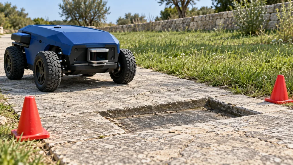
Imagine an engineering team evaluating a small wheeled inspection robot for a supervised outdoor facility route. A service path includes a shallow drainage depression and a raised expansion seam. The team is not trying to certify autonomous travel. It wants an evidence-backed answer to a smaller question: with this mount, route direction, host, and surface condition, can the team see a reviewable difference between the reference path and each measured target?
They start with a short fenced or otherwise controlled section and use a low-risk supervised mode chosen by their test lead. They document the LiDAR mounting orientation, route direction, time window, surface state, measured target geometry, and chosen MRP-LD1 data path. A run over the nominal surface establishes a reference record. They then repeat the same route through one target at a time, without silently changing both the target and the host configuration.
After capture, the team reviews raw data, parsed output, and the host-side decision together. If a sample is ambiguous, that is a legitimate result: label it, keep the record, and refine the next controlled test. Do not turn an ambiguous frame into a pass by adjusting the conclusion after the fact. For broader mobile-robot context, see the site’s LiDAR guide for AMR and service-robot navigation.
5. Make the sensor-to-decision chain observable
When a target is missed or falsely flagged, a useful test tells you where the uncertainty entered. Name the evidence at each handoff: sensor output, selected interface, host timestamp, parser or point-cloud transformation, terrain/obstacle rule, vehicle command or operator alert, and observed result. The site’s guide to validating a depth stream before navigation tuning is a good companion for checking that path before making an application claim.
Minimum evidence package
- Sensor, host, and vehicle identifiers with relevant firmware/software versions.
- Mounting pose, selected interface, coordinate convention, and a photo or drawing of the intended ground region.
- Measured target geometry, surface material/state, approach direction, and environmental observation.
- Time-aligned raw or parsed sensor record, host interpretation, and the defined output state.
- Operator observations, abort/review notes, and a configuration-change log.
Choose whether the application consumes a depth image, point cloud, or both, and make that choice explicit. The difference matters for the evidence you can inspect. The related depth-map versus point-cloud explainer can help teams state the data product they intend to review; apply the same clarity to a ground-relief route.
6. Common mistakes that make a ground-relief test misleading
- Calling a shallow feature an “obstacle” without defining the rule. A depression, curb, and seam may demand different interpretation and response logic.
- Using one attractive visualization as proof. Keep raw or parsed samples, target measurements, and conditions so the result can be reviewed.
- Changing multiple variables at once. Altering the mount, target, route angle, and host threshold together prevents useful comparison.
- Assuming a documented range proves route coverage. The product baseline is not a guarantee for your target angle, material, lighting, mount, processing, or vehicle behavior.
- Hiding ambiguous observations. An unclear return is evidence for another controlled test, not a reason to make a stronger claim.
- Skipping the host decision record. A visible point-cloud feature does not show how the selected application rule classified it or what the machine did next.
7. RFQ and evaluation checklist for a compact LiDAR field test
Before requesting product documents, SDK resources, sample data, an evaluation sample, or a project-specific quote, assemble a concise engineering brief:
- Target platform, application, mounting concept, and working-distance region.
- The ground feature to evaluate, measured geometry, surface material/state, and intended route direction.
- Indoor/outdoor condition, expected ambient environment, and the controlled test boundary.
- Host system and preferred documented interface: UART, UVC, or UDP.
- Whether the team needs depth data, point cloud, or both, plus the planned log format.
- The prewritten review question, chosen evidence fields, sample quantity, and expected project timing.
A specific brief helps the supplier and the integration team discuss the correct documents and evaluation path without assuming that a sensor module has already proven an application-level result.
Frequently asked questions
Can a compact 3D LiDAR guarantee detection of every curb or shallow depression?
No. The result depends on the feature, mounting, view, optical conditions, data path, interpretation rule, and intended machine. Use a controlled field test to establish a narrow, documented observation for your configuration.
Is a point cloud enough to prove a robot will respond correctly?
No. Review the raw or parsed data and the host-side decision separately. The vehicle response, route logic, and operator or controller behavior are additional system elements.
What should the first outdoor target be?
Choose one measured, low-risk surface feature that reflects the real question, then keep the route and mounting repeatable. Do not begin with an undefined collection of hazards.
Which MRP-LD1 output can I evaluate?
The supplied product information lists depth and point-cloud output with UART, UVC, and UDP interfaces. Choose one documented path your host can capture and explain in the evidence record.
Do the documented outdoor 0.2–8 m values prove my route works?
No. They are supplied product baselines. The target, surface angle, ambient conditions, mounting, host processing, and whole vehicle must be validated in the intended configuration.
Why record the reference surface before the target?
A reference gives reviewers a known comparison for the same mount, route, and host configuration. Without it, a visual difference may be hard to attribute to the target.
How many variables should change in a test run?
Change one named variable at a time when possible. That makes it easier to learn whether a target, approach angle, mount, surface state, or host rule changed the observation.
What if the target appears only intermittently?
Record the ambiguity and the associated conditions. An intermittent result should lead to a revised controlled test or engineering review, not an unsupported deployment claim.
What should I share when asking for an evaluation sample or quote?
Share the platform, application, ground feature, working-distance region, scene, host system, preferred interface, intended data output, sample quantity, expected timing, and the exact evaluation question.
Turn a terrain question into an evidence-based evaluation
If your team needs to evaluate compact depth and point-cloud input for a defined mobile-robot route, start with the surface feature, mount, host interface, and review question. Review the MRP-LD1 product details, then request product documents, SDK resources, sample data, an evaluation sample, or a project-specific quote with your field-test brief.