LiDAR Selection & Buying
A buyer-side power-budget checklist for compact UAV prototypes
A listed 5 V, 1.2 W distance module can be a useful starting point for a compact airframe—but it is not an endurance, current-transient, or flight-control guarantee. Use this buyer-side checklist to turn the listing into a testable power, mass, data, and evidence handoff.
Decision in one sentence: shortlist the module when its stated supply, mass, interface, field of view, and output fit the concept; release it to the airframe only after the team records measurements at the module terminals and agrees who owns the data path.
What a low power LiDAR listing actually decides
For a prototype buyer, “low power” should be a qualification question, not a label that ends the discussion. The available MRP-LD1 product entry lists a 5 V supply and 1.2 W power consumption, alongside an 8 g module mass. Those are useful inputs for an initial architecture review: they identify a candidate rail, provide a planning-level load figure, and let the mechanical owner include the sensor in a mass budget.
They do not prove battery runtime, connector voltage at the module, startup behavior, cable loss, or a working connection to a particular flight controller. If both listed electrical values were simultaneous nominal values, 1.2 W divided by 5 V is a 0.24 A planning reference—not a measured current waveform and not a required power-supply rating. The correct next step is to state the intended test condition and measure it.
This distinction matters especially for SPAD dToF evaluation. Research on SPAD-based dToF ranging precision models the effect of optical photon flux, pulse width, quantization, and detector dead time; a power number by itself cannot establish ranging precision for a particular target or illumination condition. See the ranging-precision study for the measurement context. Treat the supplier entry as a scope for an evaluation, not as a substitute for that evaluation.
| Featured-product entry | Listed value | What the buyer should do next |
|---|---|---|
| Supply / power consumption | 5 V / 1.2 W | Reserve the rail, then measure voltage at the module and observed power in agreed test states. |
| Module mass | 8 g | Include the module, mount, connector, and harness in the aircraft mass record. |
| Output | 40 × 30 resolution at 10 fps | Decide where the output is received, logged, and assessed before selecting a host path. |
| Interfaces | UART, UVC, UDP | Ask which interface and message format are available for the specific sample and intended host. |
| Field of view | 60° × 45° | Draw the intended mounting direction and check that the usable scene is actually inside it. |
| Stated range | 0.5–25 m indoor; 0.2–8 m outdoor | Write down target material, angle, ambient condition, and acceptance distance for the trial. |
Source for every product value in this table: the available MRP-LD1 Drone LiDAR Sensor product entry. The right column is an evaluation action, not an added product specification.
Turn the listed figures into an owner-by-owner handoff
A reliable purchasing decision does not ask one person to validate everything. Give each open question an owner, a record, and a release condition. That is how a compact module stays a candidate rather than becoming an undocumented assumption in the airframe.
| Owner | Question to close | Evidence to retain | Do not infer |
|---|---|---|---|
| Electrical lead | Does the installed 5 V rail stay within the team’s agreed bounds at the module connector? | Supply setting, harness revision, terminal-voltage trace, and measured power for named test states. | Aircraft endurance from the 1.2 W listing alone. |
| Mechanical lead | Can the 8 g sensor, bracket, cable exit, and field of view coexist with the payload layout? | Mount drawing, mass record, field-of-view sketch, and vibration test scope. | Clear coverage merely because a field-of-view figure exists. |
| Integration lead | Which listed interface will the sample use, and what does the receiving system expect? | Interface choice, connector/pinout confirmation, message sample, time-base rule, and log location. | Protocol or autopilot support that the product entry does not state. |
| Test lead | Which target, angle, ambient condition, and distance make the result decision-relevant? | Test card, target notes, raw logs, observed invalid states, and repeatability notes. | Outdoor or application performance from an indoor bench result. |
| Buyer | Which supplied material will make the result reproducible after a sample arrives? | Revision, product configuration, lead time, documentation request, and supplier responses. | That an unpublished detail is included by default. |
Build the bench record before an airframe decision
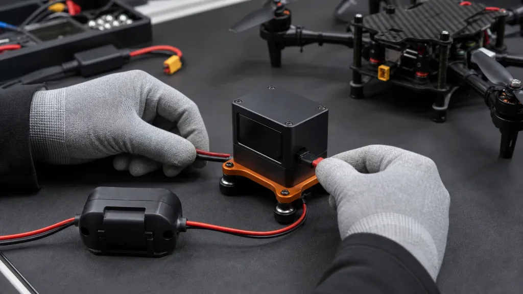
Start with a small test card that another engineer can repeat. Name the module revision and host, identify the selected interface, note the power source and cable/harness revision, and describe the target and illumination. Then capture the values at the module—not only at the power supply. That boundary keeps cable and connector effects visible to the person who must solve them.
- Set the scene: record the target material, target angle, test distance, ambient condition, and whether the sensor is stationary or moving. These details matter because optical conditions are part of a dToF result.
- Measure the installed electrical boundary: record supply voltage at the module terminals and observed power for the agreed idle, streaming, and transition states. Keep the measurement method and logging interval with the result.
- Make data visible: save a short raw capture and document how the host knows which values are valid, stale, or missing. Do not collapse that decision into a screenshot.
- Check the physical view: compare the actual mount direction against the listed 60° × 45° field of view. Photograph the test setup and note any occlusion from landing gear, payloads, guards, or wiring.
- Separate a flight decision: use the bench record to decide whether to proceed to a constrained vehicle test, not to claim a control outcome.
For a deeper bring-up checklist, review common LiDAR integration issues and how to diagnose them. If you later need a flight-specific validation plan, keep it distinct from this electrical qualification with the low-altitude control validation guide.
Keep the data contract separate from the power decision
MRP-LD1 lists UART, UVC, and UDP interfaces. That gives a buyer choices to clarify; it does not say which one a given host, controller, or software stack will accept. Ask for the selected sample’s interface details and a representative data capture, then decide which system owns conversion, validity handling, timing, units, logging, and fault behavior.
For example, if a project later chooses to map a rangefinder result into a MAVLink telemetry path, the standard DISTANCE_SENSOR definition includes fields for current distance, minimum and maximum distance, orientation, covariance, and field of view. That is a useful handoff checklist—not a claim that this module sends MAVLink or works with any specific autopilot.
Write the decision in a one-page contract: input interface and message sample; unit and coordinate convention; timestamp source; validity/timeout rule; receiving process; log destination; and the person responsible for a mapping change. The companion articles on choosing UART, UVC, or UDP and a LiDAR sensor data contract for flight-controller integration can help keep that handoff explicit.
Illustrative compact-UAV evaluation case
Scenario: A small inspection-UAV team wants a forward-facing distance input for a prototype and has reserved one 5 V accessory rail. The buyer sees the MRP-LD1’s 5 V, 1.2 W, 8 g, 40 × 30 at 10 fps, 60° × 45° listing and wants to know whether to request a sample.
Good first decision: request the sample and documentation only after the electrical owner identifies the rail and measurement point, the mechanical owner draws the proposed sightline, and the integration owner names one interface to investigate. The team agrees to test a written target/distance/illumination set, retain raw data, and review terminal measurements before taking the module outdoors.
What the team deliberately does not decide yet: flight time, obstacle-avoidance behavior, a controller setting, or final maximum usable distance. Official ArduPilot rangefinder guidance likewise warns that a configured maximum must be a tested, appropriate value; that principle is valuable even when a project uses another stack. Read the rangefinder documentation as configuration guidance, not as an MRP-LD1 compatibility promise.
Four low-power LiDAR buying mistakes to avoid
1. Treating 1.2 W as a flight-time calculation
Use it to begin a rail-budget conversation. Do not turn it into endurance without the aircraft’s own energy model, installation measurement, and operating profile.
2. Asking for “compatibility” without naming the handoff
Name the intended interface, host, required output, timestamp rule, and failure behavior. A supplier can then answer a concrete configuration question instead of a vague compatibility question.
3. Copying an indoor range line into an outdoor acceptance test
The product entry separates stated indoor and outdoor ranges. Keep target, lighting, angle, and distance in the test card so a buyer can compare like with like.
4. Leaving the evidence with one person
Store the test card, raw capture, measurement method, mount photo, and supplier response together. That makes a later airframe review faster and less dependent on memory.
RFQ and sample-evaluation checklist
- Confirm the exact module revision and the selected interface for the sample.
- Request current pinout, power-input guidance, data format, and a representative output capture for that configuration.
- State that the team will verify the listed 5 V and 1.2 W figures at the installed module boundary.
- Share the planned mounting direction and ask for any configuration-specific field-of-view or mechanical guidance.
- Define the target, distance, lighting, and success record before testing.
- Ask which documentation revision applies to the supplied sample and how changes are communicated.
Turn the listing into a sample request
Send your aircraft rail, mounting sketch, preferred interface, target distance, and test condition. Purpleriver can help identify the product information and documentation to confirm for the evaluation configuration.
Review documentation resources or contact the Purpleriver team.