UAV integration and flight-test evidence
Left Obstacle Sensing: The Yaw-Sweep Test That Exposes UAV Shadow Zones
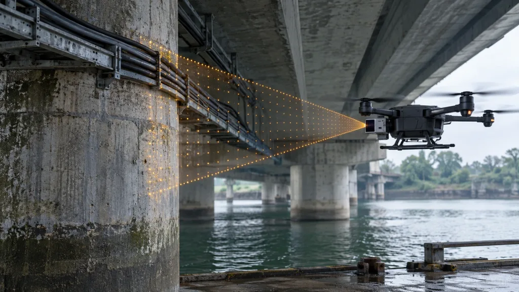
Left Obstacle Sensing is not proved when a side-mounted module reports a plausible number on a bench. It is proved when a target in the aircraft-left physical sector survives mounting shadows, reaches the controller in the declared body frame, and appears in the evidence used for the intended test mode. For an inspection multirotor passing a bridge pier or cable tray on its left, a short yaw sweep exposes gaps that a static straight-ahead demonstration misses.
Quick answer
Define aircraft-left in the flight stack’s body frame. Photograph the production-like mount, sweep a controlled target across the intended sector, retain an explicit unknown state where data is not trustworthy, and compare the sent sector record with a controller-side view or log. A module specification scopes a test; it cannot prove an installed coverage sector, data freshness, or vehicle response by itself.
Define Left Obstacle Sensing in a Body Frame, Not in a Photograph
“Left” might mean the image edge, the pilot’s left, a vehicle-facing-left bracket, or a negative yaw direction. None is adequate until the team names the vehicle body frame, sensor optical axis, and transform between them. The MAVLink OBSTACLE_DISTANCE specification provides a usable contract: a distance array with angular increment, angle offset, and a reference frame. For body-mounted data it identifies MAV_FRAME_BODY_FRD as vehicle-front aligned.
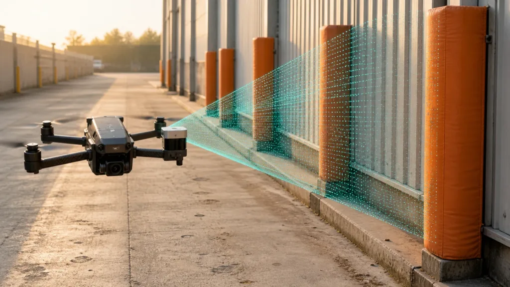
As an illustrative geometry only, a calibrated optical axis deliberately installed 90 degrees to aircraft-left can be recorded as a negative 90-degree offset. With the Featured module’s stated 60-degree horizontal field of view, a sketch may begin with a nominal -120 to -60 degree span. It is not an acceptance result: arms, gear, payloads, bracket thickness, usable-pixel masking, calibration, and target geometry can narrow the usable sector. Do not assume each of 40 output columns is an equal-angle ray without calibration evidence.
Choose Evidence for the Yaw-Sweep Test
| Question | Evidence to retain | What it establishes |
|---|---|---|
| What is aircraft-left? | Frame sketch, marked optical axis, mount photo, and transform. | A named sector rather than an ambiguous view. |
| Where are shadows? | Target positions at planned yaw steps, plus photos of arms, gear, and payloads. | Occlusion boundaries that can be repeated after a change. |
| What is delivered? | Sensor record, sector record, timestamps, validity state, and parser version. | A trace from target to converted data. |
| Did the controller receive it? | Proximity view or flight log aligned to target position and mode. | Reception without claiming a particular avoidance behavior. |
| Is it actionable? | Managed low-speed plan, controller snapshot, data age, and project criteria. | A basis to judge the intended mode and margin. |
Build a Left-Side Shadow Map Before the First Flight
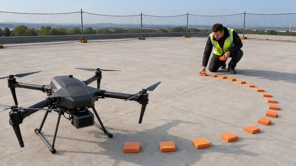
Secure the aircraft or use a non-propulsive fixture. Place a high-contrast target at a known stand-off, then move the aircraft through small declared yaw steps while keeping the target in the relevant elevation band. At each step record whether the target is observable, which sector/bin is populated, the data age, and a photo. Repeat at the target and lighting conditions that matter to the project; do not borrow a universal pass distance from a component page.
- Freeze the installation. Use the intended bracket, cable routing, guards, payload, and landing gear. A bare bench mount cannot reveal aircraft shadows.
- Make an angle ledger. List target position, aircraft yaw, body-frame target angle, record time, sector/bin, validity state, and a photo. Keep a row when the target is physically present but blocked.
- Separate clear from unknown. MAVLink reserves UINT16_MAX for unknown/not used, while max_distance + 1 means no obstacle. Turning missing data into a clear path defeats the purpose of the test.
- Aggregate conservatively. Preserve the nearest trustworthy return that matters to a sector instead of averaging away a narrow pier edge. Document the rule and quality filter.
- Repeat after physical changes. A new payload, harness, or isolation part can change the shadow map.
ArduPilot’s rangefinder setup overview distinguishes directional sources from 360-degree coverage and describes orientation for horizontal proximity sources. That is useful context, but it does not replace measuring a particular installed aircraft-left geometry.
Preserve Sector Meaning Through the Controller Handoff
Sensor output, a companion-computer conversion, and controller input are separate checkpoints. Give each a timestamp and frame declaration. If a host publishes a body-mounted obstacle map, retain the source record and outgoing message together so a reviewer can locate an error in sensing, sectorization, transport, or controller configuration.
The current PX4 Collision Prevention guide explains why this matters: its obstacle map tracks sectors with either data or no-data, and coverage, configured distance, and delay influence behavior. It also notes that the configured distance is to the sensor, not the outside of the vehicle or propellers. Therefore a project needs its own physical margin and managed test, not a copied number.
Controller-side proof is a separate gate. ArduPilot’s proximity documentation describes a real-time view, logged quadrant data, and filtering for noisy sources. On another stack, select an equivalent viewer, recorder, or flight log. Host-side data is not automatically a controller-accepted left-sector input.
Evaluate the MRP-LD1 as a Left-Looking dToF Input
The current Featured product is the MRP-LD1 Drone LiDAR Sensor. Its supplied facts can frame an evaluation, but they do not make it left-looking by default or prove flight-controller integration. Orientation, cable path, host software, and the shadow map must be verified on the aircraft.
| Featured-product field | MRP-LD1 stated value | Use in this evaluation |
|---|---|---|
| Principle | SPAD dToF; 940 nm VCSEL; solid-state architecture | Evaluate as an active depth input, not a guarantee of controller behavior. |
| Stated range | 0.5–25 m indoors; 0.2–8 m outdoors | Record target, lighting, and planned test distance. |
| Ambient-light statement | 80 klux | Log actual conditions rather than treating a stated value as an outcome. |
| FOV and output | 60° (H) × 45° (V); 40 × 30; 10 fps | Draw a nominal sector, then measure usable coverage and data age. |
| Interfaces and host support | UART, UVC, UDP; Windows, ARM, Linux, Android | Select one documented path and retain parser, framing, and timing evidence. |
| Electrical and mass | 5 V; 1.2 W; 8 g | Review the actual harness, supply, and mount. |
| Stated accuracy bands | 0.2–1 m ≤ ±3 cm; 1–5 m ≤ ±5 cm; 5–8 m ≤ ±10 cm; 8–15 m ≤ ±20 cm | Do not substitute them for installed target-and-environment validation. |
The product export also lists a Class 1 (FDA Recognized Eye-Safe) safety statement and operating temperature of -20 to 60°C. Confirm full project requirements with responsible engineering and compliance teams; this article does not turn product fields into deployment approval.
Illustrative Case: A Left-Pier Clearance Pass Under a Bridge
Illustrative integration scenario, not a customer result: an inspection multirotor moves slowly under a bridge while a concrete pier and cable tray remain on aircraft-left. Before managed flight, the team uses the yaw-sweep ledger to identify where the left-mounted sensor sees the pier, where landing gear blocks it, and what is represented as unknown in the handoff.
The stages are props-off target sweep; powered but restrained telemetry check; low-speed flight in a managed test area; then intended-mode evaluation by the responsible flight-test team. Each record pairs target position with sensor output, data age, body-frame sector, controller evidence, and active mode. This is more useful than declaring a single safe distance, because margin depends on speed, total sensing/control delay, vehicle geometry, response, and the project’s buffer.
For adjacent decisions, compare the forward-sector guide, rear-sector guide, and blind-sector handoff guide. Each covers a different boundary; none should be copied blindly into an aircraft-left test.
Create a Controller-Handoff Record Another Engineer Can Reproduce
Save a compact replay bundle: mount photo and measured axis, sensor configuration, host/firmware versions, interface choice, diagnostic data, sector rule, timestamps, controller snapshot, target placement, controller evidence, and mode state. For UART, UVC, or UDP, document the selected MRP-LD1 path rather than assuming an interface proves payload semantics. The site’s data-contract guide is a useful checklist for frames, freshness, validity, and consumers.
A useful pass statement is narrow: “At the declared yaw and target condition, the intended left sector was present, fresh enough for the project criterion, and visible in controller evidence.” A useful failure statement is just as valuable: “At this yaw, the target was physically present but occluded; output remained unknown; no coverage claim is made.”
Common Left-Sector Mistakes
- Mirroring a right-side setup without measuring it. Harnesses, payloads, and gear rarely make symmetric shadows.
- Calling missing data clear. Preserve unknown states through conversion and handoff.
- Testing a naked module. The production-like mount is part of sensing geometry.
- Using a range statement as a flight limit. Installation, target, ambient conditions, speed, delay, and controller behavior require validation.
- Saving a screenshot without frame or time. It cannot prove a sector or measurement source.
- Equating reception with avoidance. Prove intended-mode behavior separately under the project safety process.
RFQ and Evaluation Checklist
- State the aircraft-left sector, elevation band, targets, and permitted blind zones.
- Request a production-like mount review covering arms, gear, payloads, bracket, and cable shadows.
- Name the body frame, optical axis, transform, increment, and left-sector offset.
- Require a yaw-sweep ledger with photos, target positions, validity states, and controller evidence.
- Define unknown, out-of-range, invalid, and no-obstacle states.
- For MRP-LD1, identify the UART, UVC, or UDP path and request matching integration material.
- Record data age, controller configuration, physical clearance basis, and intended mode before flight.
- Ask for a report that separates sensing, conversion, reception, and vehicle-response observations.
Scope the left-sector evaluation before requesting a sample
Share the coverage map, intended mount, target conditions, host path, and controller-handoff requirement. Purpleriver can help frame an MRP-LD1 evaluation around published module facts while your integration team owns installed-system validation.