High sensitivity LiDAR is a search term that can conceal a difficult engineering question: will a depth signal stay useful when the actual target is dark, angled, textured, or partly outside the geometry used on the bench? A sensitivity label is not an acceptance result. Before an integration team creates a detection threshold, it needs a short evidence plan that ties each observation to a target, angle, distance, lighting condition, and downstream decision.
This guide is for an automation engineer, embedded developer, or technical buyer evaluating a compact dToF module for a prototype where dark surfaces or low-contrast edges matter. It does not promise detection performance, flight safety, or controller compatibility. Instead, it provides a practical way to decide whether the data is trustworthy enough to continue with integration, revise the geometry, or ask for more evidence.
| Quick answer | Use a high-sensitivity LiDAR evaluation as a controlled evidence exercise: vary target material and angle, preserve the raw outcome and test conditions, then define a threshold only after the intended mounting geometry and data handoff are visible in the record. |
|---|---|
| Best fit | Teams assessing a compact depth module before using it for dark-object awareness, edge checks, or spatial monitoring in a prototype. |
| Decision rule | Do not turn a visually convincing sample frame into a production threshold until the same condition has a defined target, geometry, ambient note, data-quality interpretation, and receiving-system owner. |
High sensitivity LiDAR: define the evidence before the threshold
“Sensitive” is not a substitute for a test condition. In SPAD-based dToF systems, ranging precision is shaped by system conditions such as photon flux, pulse width, time-of-flight quantization, and detector dead-time effects; those interactions are the reason a single good-looking capture should not be generalized into a performance guarantee. The recent primary analysis Performance Bounds of Ranging Precision in SPAD-Based dToF LiDAR is useful here because it frames precision as an operating-point problem rather than a marketing adjective.
Target properties and geometry belong in the record too. A peer-reviewed flash-LiDAR study found that return-waveform behavior can vary with distance, incidence angle, and material-related effects. Its hardware and output are not a specification for the MRP-LD1, but it is a sound reason to include dark, neutral, and angled targets in an evaluation plan rather than judging a module only against one bright perpendicular panel. See the material-properties study for that primary-source context.
A compact ToF sensor is an integration component, not a complete application. For a useful example of the fields a receiving system may need to make inspectable, the official MAVLink DISTANCE_SENSOR specification includes distance limits, orientation, field-of-view, covariance, and signal-quality concepts. The MRP-LD1 listing does not claim MAVLink output; use the specification only as a data-handoff checklist, then prove the installed geometry and host behavior in your own project. For first-pass troubleshooting, keep the site’s LiDAR integration diagnosis guide nearby, but preserve your own test evidence instead of importing assumptions.
Dark-target decision chart for an evidence-first evaluation
| Question to settle | Controlled comparison | What to record | Pause or revise when |
|---|---|---|---|
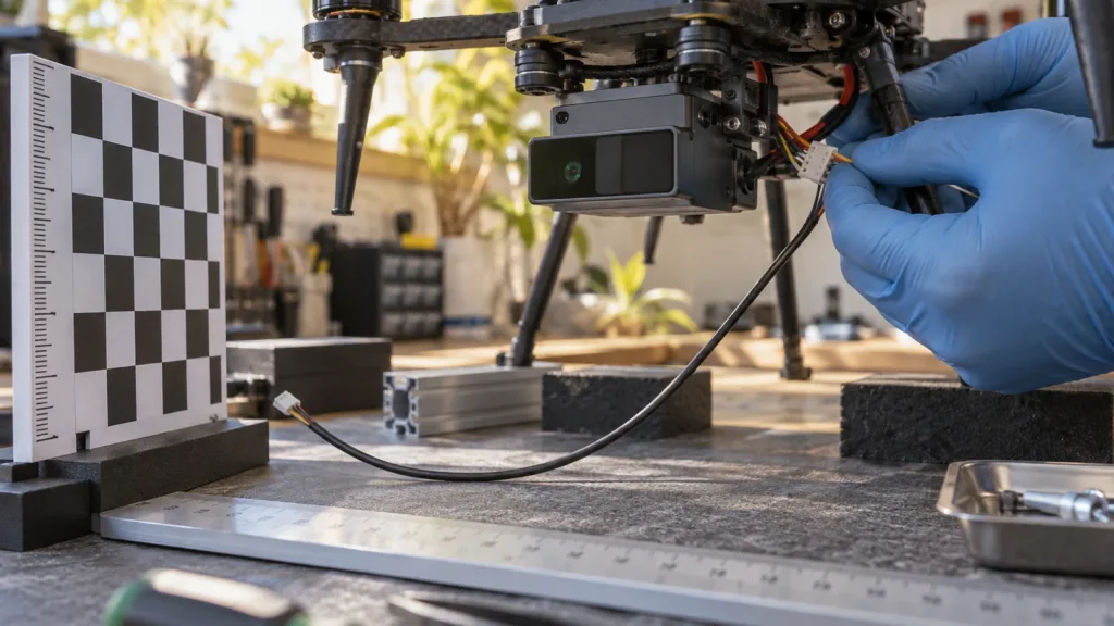
| Does the target occupy the intended sensing zone? | Place the production-like object and a neutral reference at the planned distance and mounting angle. | Mounting geometry, target bounding area, range setting, and any uncovered edge. | The target only appears after changing the geometry beyond what the installation allows. |
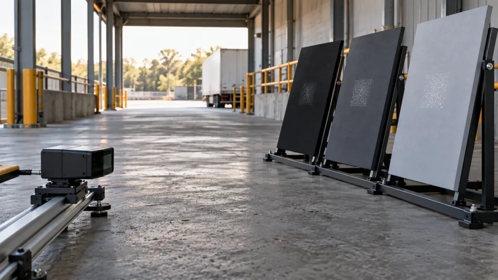
| Does a dark finish change the usable observation? | Compare matte-dark, mid-tone, and neutral reference panels with the same shape. | Raw frame or raw log reference, valid/invalid behavior, and a plain-language observation. | The team cannot state what output condition counts as usable or missing. |
| Does angle matter? | Repeat at the planned normal position and at realistic tilted or edge-facing positions. | Angle description, target distance, illumination note, and repeated-run count. | A threshold works only on the easy, perpendicular target. |
| Can another system act on the result? | Deliver the selected observation through the intended host-side path. | Interface used, timestamp policy, data owner, and error/fallback behavior to be designed. | The receiving team has no defined interpretation for missing, stale, or unexpected data. |
The aim is not to manufacture a universal pass number. It is to make the next engineering decision traceable. If an observation changes with a target’s finish or orientation, that is evidence to refine the fixture, placement, data rule, or application scope—not evidence that a module has failed or succeeded in every possible environment.
MRP-LD1 facts to keep separate from the evaluation result
The following are the exact published fields for the Featured MRP-LD1 Drone LiDAR Sensor. They identify what can be planned for; they do not certify dark-target detection, latency, an interface protocol implementation, or application safety.
| Published parameter | Listed value | How to use it in this workflow |
|---|---|---|
| Ranging approach | SPAD dToF with 940 nm VCSEL | Record the module identity and use an evaluation plan suited to an active depth-sensing component. |
| Output and frame rate | 40 × 30 output at 10 fps | Define which output condition and sequence of frames the host will save and review; do not equate frame count with detection certainty. |
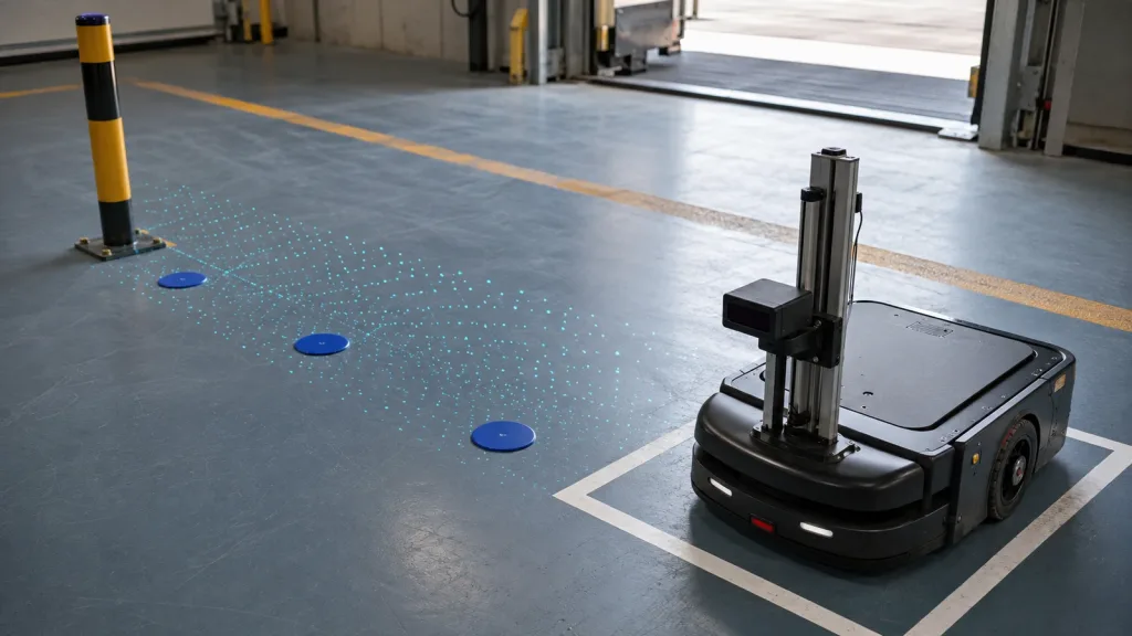
| Field of view | 60° horizontal × 45° vertical | Check whether the planned target area remains inside the installed field, including its critical edge. |
| Listed ranges | 0.5–25 m indoors; 0.2–8 m outdoors | Record the actual target distance and environment; do not extrapolate the listing into target-specific performance. |
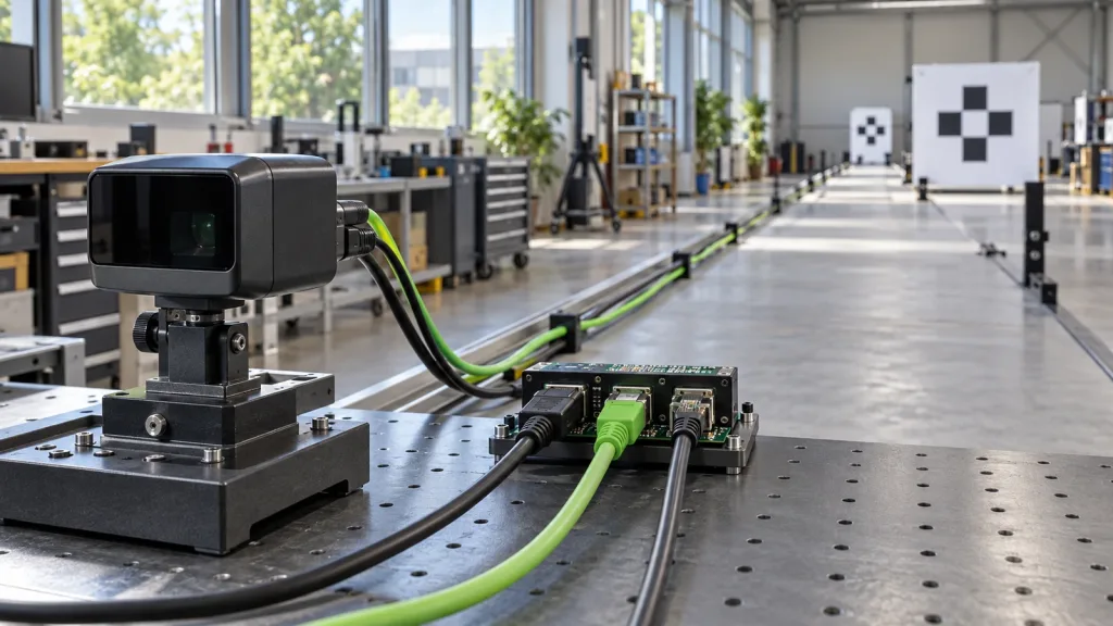
| Interfaces | UART, UVC, and UDP | Choose a host path early and document the evidence handoff, parser ownership, and failure treatment. |
| Integration fields | 5 V, 1.2 W, 8 g | Use these listed inputs in the mechanical and power review, then verify the assembled prototype. |
If the team needs help choosing an integration path, the related UART, UVC, or UDP guide explains the questions to bring to that decision. It should not replace the module documentation or a host-side test.
A six-step high-sensitivity LiDAR evidence workflow
1. Write the decision sentence first
Start with one narrow statement such as: “The prototype may continue only if the installed sensing zone produces a reviewable depth observation for the intended dark carton face and its likely tilt.” This avoids a vague objective such as “prove sensitivity.” Name what will be observed, who will review it, and what decision follows.
2. Build a small, honest target set
Use a dark matte target that resembles the relevant object, a mid-tone comparison, and a neutral reference of similar size. Include one realistic edge or tilt condition. Describe them in the log instead of assigning unverified reflectance numbers. The point is comparability: each target should occupy the same planned zone as far as practical.
3. Freeze geometry before changing settings
Photograph or sketch the mounting position, target distance, target angle, and background. Note whether the scene is controlled indoor light, shade, or an outdoor trial. Change one condition at a time. If you move the sensor and rotate the target together, the resulting frame cannot tell the next engineer what caused the change.
4. Save observations, not only screenshots
Pair each visual capture with a row in a test log: test ID, target description, distance, orientation, ambient note, selected interface, observed data condition, and reviewer decision. Where the system exposes a raw depth or point-cloud output, preserve the associated sample under the project’s data-retention rules. The site’s depth-map versus point-cloud guide can help teams name the representation they are reviewing.
5. Make missing data an explicit outcome
Do not silently discard blank, unstable, or unexpected observations. Label them as missing, ambiguous, or unsuitable for the intended decision, and retain the condition that produced them. A sound threshold needs a defined treatment for both an observation and an absence of one.
6. Hold a handoff review before application logic
Give the evidence table to the embedded or controls owner. Confirm which interface feeds the host, where records are time-associated, what the application will do when data is unavailable, and what needs a later controlled test. This separates a sensor evaluation from an unsupported claim about a robot, vehicle, PLC, or safety function.
Interface and data-handoff record
| Record field | Example entry | Why the field matters |
|---|---|---|
| Condition ID | Dark-panel / installed-angle / planned distance | Keeps comparisons from becoming unlabeled screenshots. |
| Sensor placement | Mount location, orientation description, and target zone sketch | Lets the next build reproduce geometry. |
| Host handoff | Chosen UART, UVC, or UDP evaluation path; responsible owner | Distinguishes a listed interface from an assumed application integration. |
| Data observation | Reviewable, missing, ambiguous, or needs repeat | Prevents a subjective “looks fine” judgment. |
| Decision and next test | Continue, change placement, broaden target set, or seek support | Connects evidence to a concrete engineering action. |
For a production-oriented follow-up, link the record to the site’s solid-state LiDAR quality-inspection notes. The goal is a clean boundary: the evaluation table records what your prototype observed; product facts remain those published on the product page.
Illustrative application case: matte cartons at a receiving-zone edge
Hypothetical planning example: A warehouse-automation team wants to assess whether a compact depth module is worth further prototype work near a receiving-zone edge where some cartons have matte-black print and a folded corner. The team mounts the candidate module where space permits, places three similarly sized panels—matte dark, mid-tone, and neutral—at the proposed distance, then repeats the observation with the dark panel slightly tilted.
The first deliverable is not a claim that every carton will be detected. It is a shared evidence folder and one-page review table: which panels generated a reviewable observation, what the installed geometry was, which interface carried the data, and what needs testing next. That lets the purchasing and controls teams decide whether to continue with a fuller fixture, alter placement, or request technical clarification.
Common mistakes and an RFQ checklist
- Calling the keyword a specification: “High sensitivity” is a search phrase, not a product-specific acceptance value.
- Testing only a bright, square target: include a dark production-like surface and a plausible angle or edge.
- Changing every variable at once: vary target or geometry one at a time so observations remain interpretable.
- Using a screenshot as a data contract: state who receives the data and how missing or ambiguous observations will be handled.
- Promising application behavior too early: verify the assembled system rather than inferring safety, controller, or detection performance from a module listing.
| Ask before an RFQ or evaluation request | Why it belongs in the request |
|---|---|
| What target material, size, distance, and angle represent the intended object? | It defines a reproducible evaluation instead of an abstract sensitivity request. |
| Which published module fields must fit the enclosure, power budget, and host? | It keeps mechanical and interface planning tied to the listed product facts. |
| Which data representation and interface will the host team review? | It assigns an integration owner before a sample becomes a disconnected demo. |
| What is the planned treatment for missing or ambiguous data? | It exposes decision logic that cannot safely be improvised after installation. |
| Which physical test conditions need technical support or documentation review? | It gives Purpleriver a precise, evidence-based starting point for a discussion. |
Turn a sensitivity question into an evaluation brief
Bring your target photos, intended geometry, host interface preference, and the questions your evidence record must answer. Purpleriver can help you start from the listed MRP-LD1 module facts and discuss an evaluation path without turning an early prototype observation into an unsupported performance promise.