LiDAR selection for integration teams
Compare the installed sensing job—not two architecture labels
To compare solid state lidar vs mechanical lidar usefully, begin with the coverage your machine must own, the physical beam-steering method inside each candidate, the usable data path, and a test record. A label on a quotation cannot prove that a sensor will see the required zone, fit the mounting envelope, deliver usable data to the host, or support a system-level safety decision.
This guide gives an engineering buyer a deployment-fit scorecard. It is deliberately not a claim that one architecture wins in every drone, robot, or inspection project.
Quick answer
Choose the candidate that passes a written coverage, packaging, data-handoff, and evidence plan for the actual deployment. A rotating mechanical scanner may be evaluated when broad scene coverage is genuinely required; a compact directional solid-state module may be evaluated when the required zone, mass, power, and host path are bounded. In either case, ask for the device’s actual steering mechanism and validate the installed output with representative targets. Do not treat nominal field of view, a port list, or a category name as acceptance evidence.
1. Name the beam-steering architecture before comparing it
“Mechanical” and “solid-state” are useful starting words, but they are not a complete test plan. Ask the supplier to identify how the outgoing beam is directed, what moves in normal operation, whether steering is rotating, galvanometer-based, MEMS-based, optical-phased-array-based, flash, or hybrid, and what the stated coverage is under the proposed settings. NIST’s lidar measurement material explicitly separates beam-steering categories such as mechanical, MEMS, solid-state, and hybrid; it also frames field of view, wavelength, detector, range, and resolution as separate variables worth stating in a comparison.
A recent peer-reviewed review describes conventional mechanical scanning with rotating mirrors and discusses compact solid-state approaches such as MEMS and optical phased arrays. That background is helpful, but it does not make all sensors in either group equivalent. The buyer’s question is not “Which label is modern?” It is “What steering and measurement behavior is this specific device able to demonstrate in the installed job?”
For a high-level site introduction, see the existing solid-state LiDAR versus mechanical LiDAR for UAV platforms. The scorecard below adds a different layer: it turns the comparison into a traceable deployment decision rather than another general pros-and-cons list.
2. Compare solid state LiDAR vs mechanical LiDAR with five evidence questions
| Decision question | Evidence to request | What not to infer |
|---|---|---|
| Which physical zone must be observed? | Installed coverage drawing, target positions, occlusion notes, and the candidate’s configured field of view. | A nominal maximum field of view is not proof that the mounting, housing, or platform leaves every required zone visible. |
| How is the beam directed? | Specific steering architecture, moving-part description, scan pattern, frame/update behavior, and relevant configuration. | A sales label does not establish the mechanical details of every candidate or its behavior over time. |
| What must fit on the host machine? | Mass, dimensions, power input, thermal and mounting constraints, cable routing, and the platform’s own allowance. | A small sensor alone does not prove a finished payload or vehicle integration is suitable. |
| What reaches the software stack? | Sample captures, timestamp convention, coordinate frame, units, invalid-value behavior, transport framing, and restart behavior. | Listing UART, UVC, or UDP does not prove a native driver, controller protocol, or application-ready output. |
| What will count as acceptance? | Representative targets, ranges, angles, lighting, motion, failure cases, raw recordings, and pass/fail owners. | A polished demonstration is not an acceptance result for a different mounting position or operating envelope. |
The distinction matters because beam steering is only one part of the result. The peer-reviewed Laser & Photonics Reviews overview notes why the reliability, size, and cost implications of mechanical rotation motivate solid-state research. Treat that as a reason to ask better questions—not as permission to promise that an unnamed solid-state device will meet your range, coverage, cost, or lifetime target.
3. Map usable coverage before choosing a form factor
Start with objects and spaces, not sensor categories. Draw the vehicle or mounting surface, the optical center, protective window, cables, propellers or chassis edges, expected attitude changes, and the zones the system needs to observe. Then place representative physical targets at the nearest, farthest, highest, lowest, and most oblique required positions. Include the materials, lighting transitions, surface angles, motion, and contamination conditions that matter to the deployment.
A broad rotating scan may be worth evaluating if the system truly needs continuity around a platform. A directional module may be worth evaluating when the protected decision zone is bounded and its orientation can be controlled. Neither sentence is a recommendation for a particular part. It tells the team where to focus its proof: required coverage and usable returns in the installed geometry.
Keep three layers separate in the record:
- Geometric reach: which rays could intersect a target in the proposed mounting position.
- Measured output: which returns remain valid for the target, scene, configuration, and environmental condition.
- System response: how the host interprets age, confidence, dropouts, transforms, and its own operating policy.
Only the first layer can be approximated from a drawing. The second needs captures; the third needs an integration test. For an independent review of beam-steering platforms and their tradeoffs, use the current Sensors review of solid-state LiDAR principles alongside the specific device documentation.
4. Review the data handoff, not only the connector
Architecture comparisons often stop at optics, then fail at integration. Ask for a short raw capture from each candidate with a companion manifest: firmware and configuration identity, clock source, acquisition-versus-reception timestamp meaning, coordinate convention, units, frame dimensions, invalid values, confidence fields, packet loss behavior, and restart sequence. Keep the parsing tool or protocol reference with the capture.
That record lets an engineering team reproduce an observation instead of arguing from screenshots. It also avoids an easy category error: a sensor may expose a usable transport yet still require host-side parsing, conversion, time alignment, and application validation. The UART, UVC, or UDP interface guide can help organize the transport question; it should not be read as a promise of a particular flight-controller, ROS, or navigation-stack integration.
NIST’s comparison-oriented work is a useful discipline here: record the test method and the variables that can change the outcome. The NIST lidar measurement presentation shows why field of view, wavelength, detector, steering, and measurement conditions cannot be reduced to a single architecture label.
5. MRP-LD1: exact listed facts and the evaluation boundary
Purpleriver’s Featured product is the MRP-LD1 Drone LiDAR Sensor. The table below is a product-fact reference for an evaluation request. It is not a device-versus-device result and it does not establish a complete vehicle or robot outcome.
| Listed field | MRP-LD1 value | What the buyer should still validate |
|---|---|---|
| Ranging and scan principle | dToF; SPAD | The candidate’s installed output quality and the host’s use of it. |
| Optical source | 940 nm VCSEL | The final application’s optical, environmental, and compliance requirements. |
| Listed ranging capability | 0.5–25 m indoors; 0.2–8 m outdoors | Representative target, angle, light, mounting, and data-validity conditions. |
| Field of view | 60° horizontal × 45° vertical | Actual installed coverage after bracket, window, chassis, and attitude effects. |
| Output and rate | 40 × 30; 10 fps | Whether those samples and timing meet the project’s own target and response requirements. |
| Interfaces | UART, UVC, UDP | Protocol version, parsing, bandwidth, timestamps, and host-side recovery behavior. |
| Power and mass | 5 V; 1.2 W; 8 g | The complete platform budget, harness, thermal design, and mounting solution. |
| Laser safety listing | Class 1 (FDA Recognized Eye-Safe) | The project’s product-specific risk, regulatory, and system-compliance review. |
The product listing names UAV obstacle avoidance, altitude hold, terrain following, robot navigation, SLAM, AR/VR auxiliary focusing, industrial inspection, and security as application scope. That is useful for scoping a conversation, but it is not evidence that a finished aircraft, robot, or inspection process meets a required outcome. For a broader platform checklist, use the LiDAR sensor for drone selection guide.
6. Illustrative case: one bounded inspection route, two evidence requests
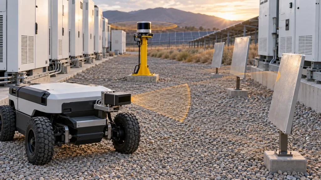
Illustrative planning scenario—not a customer result: a systems team is designing a compact autonomous cart for a solar-inverter service corridor. Its question is not whether one architecture is universally better. It needs to know whether the route requires wide contextual coverage around the cart, or whether a defined forward-and-side equipment zone can be owned by a directional sensor installation.
The team marks the route boundary, cabinet edges, low cable loops, angled metal panels, and turnaround points. It creates two comparable requests. For a rotating candidate, it asks for the configured scan pattern, installed occlusion map, and raw captures through the complete turn. For a directional candidate, it asks for the actual beam-steering description, optical-center drawing, coverage captures at every marked target, and the same host-side data manifest.
It then scores both evidence bundles against the same acceptance matrix: each required target has a named test condition, raw capture, parser version, observed validity decision, and an owner for any exception. If a required target is missed, the team records the gap instead of changing a generic “solid-state” or “mechanical” score. If the MRP-LD1 is on the short list, its listed FOV, output, rate, interfaces, 5 V input, 1.2 W consumption, and 8 g mass become inputs to that evaluation—not guarantees that it fits the cart.
This makes the eventual choice reviewable. It also produces a better RFQ because the supplier sees the target geometry, conditions, data expectations, and unresolved questions rather than only a request for “the best LiDAR.”
7. Common comparison mistakes
- Equating “solid-state” with one physical design. Request the actual steering mechanism and motion description.
- Using a headline FOV as the coverage decision. Mounting, protection, edge validity, attitude, and occlusion can change usable coverage.
- Comparing data rates without data age. Record acquisition, transport, parsing, queueing, and recovery behavior.
- Testing only a clear, front-facing target. Include size, material, angle, range, lighting, motion, and platform geometry that matter to the job.
- Turning a port list into a compatibility promise. Confirm protocol, host software, units, frames, and the conversion work actually required.
- Using listed range as an operating guarantee. Treat it as a specification input; validate the complete required scene.
- Calling perception coverage a certified safety function. Keep sensing evidence separate from the system’s risk process and applicable safety architecture.
- Accepting a demo without replay material. Keep raw output, configuration identity, and conditions with the result.
8. RFQ and evaluation-sample checklist
Before asking for a sample, send the following as a single package:
- the vehicle or machine drawing, proposed optical-center location, protected window, cable path, permitted mass/power envelope, and expected attitude changes;
- the required observation zones, minimum relevant targets, ranges, materials, angles, lighting transitions, and contamination conditions;
- the exact steering architecture, scan pattern, configured field of view, and a statement of any moving components requested for each candidate;
- raw sample output plus firmware, configuration, protocol, timestamps, units, frames, invalid values, confidence fields, and parsing reference;
- host hardware, operating system, selected UART/UVC/UDP path, bandwidth, restart, loss detection, and recovery expectations;
- an acceptance matrix with target ID, condition, raw-file name, observed result, exception, retest owner, and decision owner; and
- questions about brackets, windows, thermal design, environmental exposure, connectors, and compliance scope that the product listing does not answer.
Pair this with the LiDAR module evaluation-sample checklist. For a UAV-specific application discussion, the UAV navigation and obstacle-avoidance solution context is a useful starting point, not a safety or performance guarantee.
Turn the architecture question into an evidence request
Share the required coverage zones, mounting sketch, power and mass budget, host platform, preferred interface, representative targets, and the raw-data questions your team needs answered. Purpleriver can help compare those requirements with the MRP-LD1’s published fields and prepare a focused evaluation discussion.