AR VR Depth Module: An Occlusion-Confidence Test Plan for Interactive Prototypes
An AR VR depth module is useful only when the intended spatial task has evidence behind it. A visible depth overlay is not that evidence. Before a team assigns a compact depth input to an interactive prototype, it should prove four separate things: the capability is available, the spatial representation has usable coverage, the chosen interaction zone behaves as intended, and the experience has a defined fallback when depth is missing or uncertain.
This guide is for prototype leads who need a small, repeatable review rather than a broad claim about mapping, tracking, headset safety, or end-user performance. It treats active depth as one input to a larger experience stack.
Quick answer
Start an AR/VR depth-module evaluation with a narrow scene task: for example, decide whether a virtual annotation should disappear behind a real panel in a defined reach zone. Capture the depth output, inspect its spatial representation and gaps, log the interaction-zone result under several controlled scene conditions, and specify what the prototype does when the evidence is unavailable. Only then decide whether to expand the prototype.
How an AR VR Depth Module Fits a Prototype Decision
Depth is not a substitute for defining the experience. Decide first which real-world relationship the prototype needs to observe: a near object crossing an interaction zone, a virtual object remaining behind a physical surface, or a spatial point representation that a developer needs to inspect. Apple’s scene-depth documentation is a useful platform-specific example: it checks whether the capability is supported and associates depth with the camera frame. That is a sensible evidence pattern, not a statement that every depth module or host behaves the same way.
| Evidence layer | Question to answer | What to record | Decision if it fails |
|---|---|---|---|
| 1. Availability | Can the chosen host acquire the intended depth output in this build? | Interface, host build, capture start/stop result, timestamp convention | Do not judge interaction behavior; resolve the data path first. |
| 2. Representation | Does the output describe the test scene well enough to inspect the relevant surfaces? | Depth frame or point representation, missing areas, target material, distance, lighting note | Change the scene, mounting, data handling, or use case; do not fill gaps by assumption. |
| 3. Interaction zone | Does the defined near-field task behave consistently in the intended zone? | Panel position, zone boundary, motion state, expected versus observed prototype behavior | Keep the feature experimental or narrow the claim until repeatable evidence exists. |
| 4. Fallback | What does the prototype do when depth is absent, stale, or outside the selected zone? | Fallback state, user-visible behavior, log marker, recovery path | Do not ship an interaction that silently assumes valid spatial input. |
This separation prevents a common error: treating a colorful visualization as proof of occlusion, scene understanding, or user-experience quality. For a representation review, Apple’s scene-depth point-cloud example illustrates why a team can inspect spatial samples and gaps instead of looking only at the camera image. It is a reference workflow, not a product compatibility statement.
Documented Product Facts to Use in an Evaluation Request
Use the following facts only as supplied for the Featured MRP-LD1 Drone LiDAR Sensor. They help define an evaluation request; they do not establish suitability for a particular headset, spatial-mapping workflow, or interaction feature.
| Documented field | MRP-LD1 value | Evaluation question |
|---|---|---|
| Architecture | Solid-state SPAD dToF LiDAR module with 940 nm VCSEL | Which scene and target conditions should be captured in the test record? |
| Output | Real-time depth images and 3D point-cloud data | Does the prototype need a depth image, a point representation, or both for review? |
| Resolution and frame rate | 40 × 30; 10 fps | What spatial detail and timing evidence does the chosen interaction actually require? |
| Field of view | 60° (H) × 45° (V) | Does the planned interaction zone sit inside the mounted module’s documented view? |
| Documented range baseline | Indoor 0.5–25 m; outdoor 0.2–8 m | Which distances will be tested rather than assumed? |
| Interfaces and listed software support | UART, UVC, UDP; Windows, ARM, Linux, Android | Which documented host path will be requested and validated first? |
The supplied product description lists AR/VR auxiliary focusing among application groups. It also states that the module supplies depth and point-cloud data; a complete experience still requires host processing, application logic, and validation. Ask for the relevant manual, SDK resources, and sample data through the documentation page and sample-dataset request page before committing to an interface design.
An Illustrative Occlusion-Confidence Review
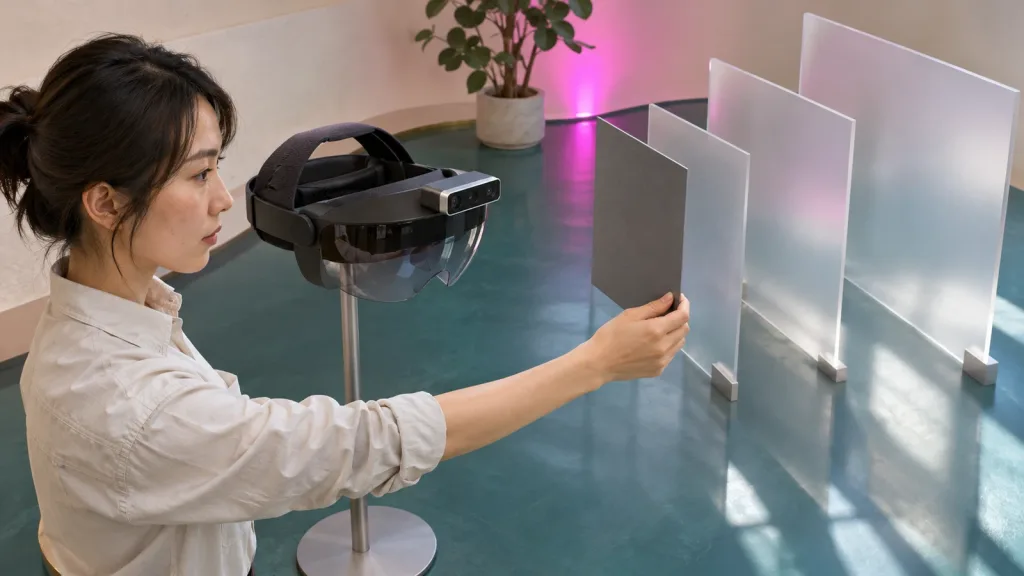
Consider an illustrative mixed-reality prototype in which a virtual marker must disappear when a neutral gray panel sits between the user and a physical work surface. This is a prototype test scenario, not a claim about any product’s occlusion quality. Mount the depth source in the planned orientation, place the panel at three documented positions across the intended reach zone, and record a still scene plus a slow panel movement at each position.
For every run, retain the capture identifier, scene lighting note, panel material and angle, source-to-panel distance, representation screenshot or export, prototype result, and fallback result. Then repeat a limited set of deliberately different conditions—such as a matte panel versus a partly reflective panel, or static versus slow movement—without silently changing several variables at once. The goal is not to manufacture a pass rate; it is to learn where the prototype’s evidence is sufficient and where it is not.
A current peer-reviewed analysis of SPAD dToF ranging notes that system behavior can be influenced by factors including timing, received photon flux, and pile-up effects. See Performance Bounds of Ranging Precision in SPAD-Based dToF LiDAR. That source supports careful scene-condition logging; it does not predict results for the MRP-LD1 or an AR/VR prototype.
Data, Interface, and Host Handoff
Choose one documented interface for the first review and write down the contract before the test. The contract should name the input type, source frame or mounting reference, capture timestamp convention, representation used by the prototype, validity signal, dropped/stale-data handling, and the owner of each transformation. If the host sees depth and the application sees only a simplified scene object, preserve an inspection path back to the original capture.
Do not blend depth-map and point-cloud discussions into one unexplained artifact. A depth-map-versus-point-cloud review can help the team name the representation it is inspecting, while the site’s guide to visualizing dToF depth data offers complementary early-test context. For a related but intentionally different near-field and host-fit angle, see the existing AR/VR depth dToF module guide.
- Capture: retain a raw or replayable example for each representative scene.
- Transform: identify where the prototype changes coordinate, scale, confidence, or representation.
- Consume: define exactly which interaction or visual behavior reads the transformed input.
- Recover: state how the experience behaves when the input is absent, stale, or outside the test zone.
Common Mistakes That Make a Depth Demonstration Misleading
- Calling a depth overlay an occlusion result. Inspect the spatial representation and record the actual interaction outcome.
- Testing only one friendly surface. Note material, angle, lighting, distance, and motion so the result has boundaries.
- Assuming a module is a full AR/VR system. Keep sensing, host processing, application behavior, and user-experience claims separate.
- Skipping the fallback. A prototype needs a visible, logged behavior for missing or uncertain input.
- Choosing an interface after writing the application. Confirm the documented capture path and data contract first.
- Turning a small test into a safety claim. This evaluation is evidence for a prototype task, not certification or a guarantee of collision avoidance or user safety.
AR/VR Depth-Module RFQ and Evaluation Checklist
- Describe the single spatial task, interaction-zone size, and user-visible outcome to evaluate.
- State whether the first evidence review needs a depth image, point-cloud data, or both.
- Provide the intended mounting orientation, host platform, and one preferred documented interface.
- List the scene distances, target materials, lighting conditions, and motion states to include in the log.
- Request product documentation, SDK resources, and representative sample data before assuming a data format.
- Define the capture-to-application ownership chain and the stale/missing-data fallback.
- Specify how the team will review spatial gaps and the intended interaction outcome.
- Record the project stage, sample quantity, and evaluation timing when requesting a project-specific quote.
Turn the prototype question into an evidence request
Send Purpleriver the intended AR/VR task, scene distance, target materials, host system, preferred interface, sample quantity, and project timing. The team can then request the relevant product documents, SDK resources, sample data, evaluation sample, or project-specific quote.
Request documentation, sample data, or an evaluation discussion