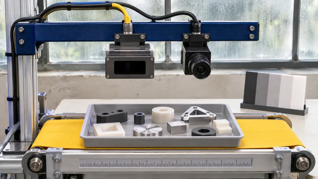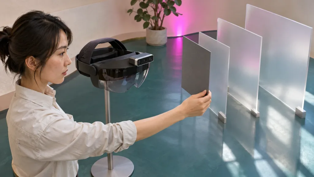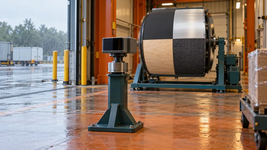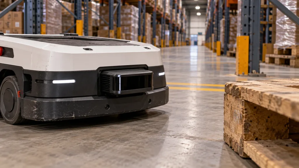
AGV AMR navigation LiDAR module decisions often go wrong before a robot moves: a compact depth sensor is asked to be a mapper, a local obstacle observer, and a complete safety function at the same time. Those are different jobs with different evidence. This guide gives warehouse-robot teams a practical way to define the sensor’s job, the host handoff, and a bounded pilot before choosing architecture.
Quick answer
Use a compact LiDAR module first as a measurable input to one declared navigation job—not as proof of an entire navigation or safety system. For an AGV/AMR pilot, state whether the module is being evaluated for near-field obstacle observations, a depth-to-point-cloud handoff, or a mapping/localization pipeline; preserve time and frame information; then test representative pallet, rack, floor, motion, and stale-data cases on the complete robot.
1. Define the AGV AMR Navigation LiDAR Module Job Before You Test It
“Navigation LiDAR” is not a single requirement. An AMR can combine odometry, a map or localization source, local obstacle observations, a planner, a controller, and a project-specific risk process. A module evaluation is clearer when its success criterion belongs to one layer. This also prevents a good raw depth capture from being mistaken for a validated stop behavior.
| Declared job | Useful first question | Evidence to retain | What it does not prove |
|---|---|---|---|
| Near-field obstacle observation | Does the installed sensor preserve enough valid observations of the required pallet toe, rack leg, tote, or pedestrian surrogate through the intended approach? | Raw captures, mount transform, target dimensions/materials, distance/angle/light cases, data age and dropouts. | Global localization, route planning, braking performance, or a complete safety function. |
| Depth/point-cloud handoff | Can the host unambiguously interpret coordinates, units, invalid values, timestamps, and confidence? | Protocol version, sample messages, clock origin, frame convention, conversion code version, and replay result. | That the host stack has a production-ready navigation driver or correct filter settings. |
| Mapping or localization input | Does the observation geometry and update behavior support the chosen estimator in representative warehouse structure? | Repeatable routes, pose reference method, transforms, drift/relocalization cases, and an acceptance metric set by the project. | That every solid-state sensor can replace a mapping LiDAR in every facility. |
| Protective function input | What formal risk, response, diagnostic, and validation evidence is required for the machine and jurisdiction? | The responsible team’s safety architecture, requirements, validation record, and applicable compliance evidence. | That a module listing or a navigation demonstration provides certification for the completed machine. |
For costmap-specific configuration and transforms, the site’s AGV/AMR costmap-input and frame-alignment guide is a useful companion. The distinction here is earlier: decide which job the data must do before setting a filter or selecting a mount.
2. Start With Exact Published Module Facts—Then Add Project Tests
The featured MRP-LD1 Drone LiDAR Sensor is a compact solid-state SPAD dToF module intended for embedded depth-perception evaluation. Its listed values are screening inputs, not warehouse acceptance limits. Target reflectivity, angle, window condition, ambient light, vibration, host processing, mounting, and robot motion must be tested in the intended installation.
| Published MRP-LD1 parameter | Listed value | How to use it in an AMR evaluation |
|---|---|---|
| Ranging principle / scanning principle | dToF / SPAD | Record the exact sensor and firmware under test; do not infer host-side navigation behavior from the principle alone. |
| Field of view | 60° (H) × 45° (V) | Draw the installed view against chassis overhang, low targets, rack legs, and the required near/far zone. |
| Resolution and frame rate | 40 × 30; 10 fps | Measure target persistence and end-to-end data age at the host rather than treating either number as an application guarantee. |
| Range baseline | 0.5–25 m indoor; 0.2–8 m outdoor | Bracket the required target distances with representative surfaces and angles; retain failures as well as successful frames. |
| Output and interfaces | Depth images and 3D point-cloud data; UART, UVC, UDP | Choose one transport and document parsing, time, units, frames, loss detection, restart, and recovery. |
| Integration constraints | 8 g; 1.2 W; 5 V; Windows/ARM/Linux/Android software support | Use these values in the mechanical/power/host screening record; confirm the current software and protocol scope for the project. |
These facts support a test brief. They do not establish native ROS output, a complete AGV navigation package, mapping performance, or a safety-rated machine. If your team needs an interface comparison first, see the UART, UVC, and UDP LiDAR interface guide.
3. Build an Evidence Plan Around the Declared Role
Make the pilot small enough to learn from. A near-field observation pilot can be successful even if the mapping stack remains unchanged; a mapping pilot can be deferred until the team knows the data contract is repeatable. The table below turns that separation into gates.
| Gate | Near-field observation pilot | Mapping/localization investigation |
|---|---|---|
| Physical scene | Required low and tall obstacles, actual pallet geometry, aisle edges, floor transitions, lighting and window condition. | Representative aisles, cross-aisles, racks, open areas, route repeats, and changing warehouse structure. |
| Mount | Optical-center location, pitch/yaw, chassis occlusion, cable strain, and tolerance. | The same transform record plus view overlap and route-dependent geometry. |
| Raw-data question | Does the target remain observable before the project-defined local margin? | Does the observation provide repeatable geometry for the chosen estimator and map? |
| Host question | Are observations current, transformed, filtered, and aged as declared? | Are time, frame, synchronization, and estimator assumptions stable across repeated routes? |
| Failure exercise | Cover the window, interrupt the stream, introduce a reflective target, and log recovery. | Repeat routes after a transform, map, odometry, or environment change; record relocalization and drift behavior. |
Official Nav2 Obstacle Layer documentation describes observation-source parameters such as sensor frame, obstacle height, marking, clearing, obstacle range, and raytrace range. Treat those as configuration choices to validate against the pilot lane—not universal values to copy. A limited field of view can also change the useful scene during turns; a peer-reviewed solid-state-LiDAR SLAM study identifies limited FOV as a challenge for existing LiDAR SLAM approaches. That paper does not predict MRP-LD1 performance, but it is a reason to test more than a straight static aisle.
4. Make the Data Handoff Testable Before You Tune Navigation
A clear handoff answers: what was seen, from where, and when? The ROS 2 PointCloud2 message definition documents a timestamp and coordinate-frame header, organized-cloud dimensions, field layout, binary data, and an invalid-point indicator. It also notes that 2D organized clouds can be produced by time-of-flight depth sensors. That is a message-format reference, not evidence that a module supplies this message natively.
For every capture path, write down the sensor frame; measured transform to the robot base; acquisition versus receive versus publish time; clock source; depth unit; point-field layout; invalid or low-confidence convention; packet-loss behavior; and the driver, firmware, host, and parameter versions. The depth-map versus point-cloud guide can help the team decide which representation is easier to inspect before committing to conversion.
Keep local observations separate from map claims
In a useful first pilot, replay a saved stream through the chosen local-obstacle path and compare it to the raw record. If a pallet toe disappears, determine whether the sensor never observed it, a transform moved it, a filter removed it, a timeout marked the source stale, or the planner/controller made a separate decision. This is more actionable than declaring the module “good” or “bad” after a single navigation run.
5. Illustrative Case: A Low Pallet Toe at a Cross-Aisle
Illustrative engineering scenario—not a customer result: A warehouse AMR uses a separate established localization path and is evaluating a compact forward-facing dToF module as a near-field observation input. Its team is concerned about a short pallet toe that can appear during a cross-aisle turn, not about replacing the existing map source.
Before driving, the team records the optical-center position, measured transform to the base frame, pitch, cable route, chassis edge, and all candidate targets. It captures stationary sequences with the pallet toe at several distances and yaw angles, then repeats the same matrix with a reflective wrap, a dark tote edge, and a doorway-light transition. For every sequence it keeps raw depth/point data and the host-side converted result.
Next, it performs controlled low-speed approaches and turns with a project-defined operating margin. It logs sensor acquisition time, host receive time, converted-message time, target visibility, robot state, and stream interruptions. A covered-window and disconnected-stream test establishes what the host does when the observation is unknown. The team can then decide whether the local-observation role is useful, what conditions bound it, and which unanswered questions belong in the next supplier or systems review.
For a wider system view, the site’s robotics 3D-mapping solution page and LiDAR-for-robotics coverage and host-handoff guide provide related context. Keep the pilot result bounded: it is evidence for the declared role and tested conditions, not a promise of warehouse-wide behavior.
6. Common AGV/AMR LiDAR Module Mistakes
- Calling all point clouds “navigation.” Name the job: local observation, transport conversion, mapping, localization, or a protective function input.
- Using nominal range as an acceptance distance. Target material, angle, mounting, motion, light, and the full processing path need physical evidence.
- Testing only an upright carton. Include the low, narrow, wrapped, dark, reflective, and angled targets the project actually needs to manage.
- Saving only filtered output. Preserve a raw capture so a missing point can be traced to acquisition, conversion, transform, filtering, or downstream behavior.
- Leaving time semantics unstated. A convincing-looking cloud can still be too old, repeated, or associated with the wrong robot pose.
- Hiding a transform assumption in code. Record the optical frame, base-frame transform, direction convention, and calibration version with the test result.
- Tuning a costmap before proving the mount. Chassis occlusion and pitch may remove the needed view before any navigation parameter can help.
- Equating an integration demo with a complete safety case. The completed machine requires its own architecture, risk process, response validation, and applicable compliance evidence.
7. RFQ and Evaluation Checklist for a Warehouse-Robot Pilot
- State the robot type, operating speed envelope, current localization source, and the single module role you want to evaluate.
- Provide the mount height, pitch/yaw tolerance, chassis occlusion sketch, available power, host platform, and intended UART, UVC, or UDP path.
- List target dimensions, materials, reflectivity, approach angles, aisle geometry, lighting transitions, floor states, dust, and window conditions.
- Define the required observation zone and a project-owned acceptance measure; do not substitute it with a marketing range claim.
- Request current protocol, SDK, firmware, sample data, data-unit, timestamp, frame, invalid-value, and confidence documentation through the documentation resources.
- Ask how the system detects packet loss, reports a stopped stream, restarts, and records the versioned configuration.
- Set a representative test matrix before the sample arrives, including negative cases and raw-data retention.
- Keep mapping/localization, local-obstacle observations, controller behavior, and the project’s safety process as separately owned review items.
Turn Your Warehouse Scene Into a Bounded Evaluation Brief
Share the robot type, declared sensor role, lowest and tallest required targets, mounting envelope, indoor or outdoor conditions, host platform, and preferred interface. Purpleriver can help you compare those requirements with the MRP-LD1’s published parameters and prepare questions for an evaluation sample.