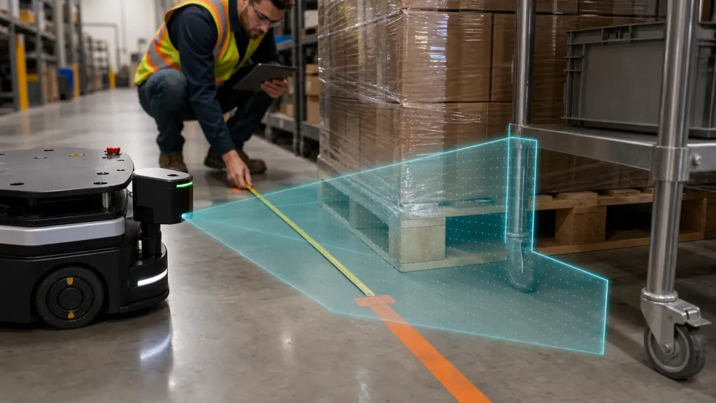
LiDAR for Robotics should not be approved from a max-range headline, a clean demo aisle, or a vague promise that the host stack can be wired up later. A compact robot program needs three things proven early: the sensor covers the real hazard geometry, the depth output stays useful on the target materials that matter, and the data path reaches a navigation or avoidance stack without turning into a side project.
This guide is written for robotics integration leads, technical buyers, and embedded-perception engineers who need to decide whether a compact solid-state dToF LiDAR module is ready for a pilot build on a real robot.
| Quick answer | Use a compact solid-state LiDAR for a robot pilot only after you validate the real obstacle geometry, the sensor's depth behavior on your actual target materials, and the first stable handoff into your host software or controller. |
|---|---|
| Best fit | AMR, inspection-cart, robotics-perception, and hybrid robot or UAV teams evaluating a lightweight depth module before a pilot build. |
| Decision rule | If the supplier can quote range, FoV, and interfaces but cannot show replayable evidence from your aisle geometry and host path, the module is not pilot-ready yet. |
What LiDAR for Robotics needs to prove before a pilot build
The term LiDAR for Robotics often gets reduced to a short spec list: range, FoV, frame rate, and maybe one integration screenshot. That is not enough for a pilot decision. A robotics team needs proof that the sensor resolves the physical depth differences that matter in its scene, keeps enough usable coverage on awkward geometry, and reaches the host stack in a form the robot can actually consume.
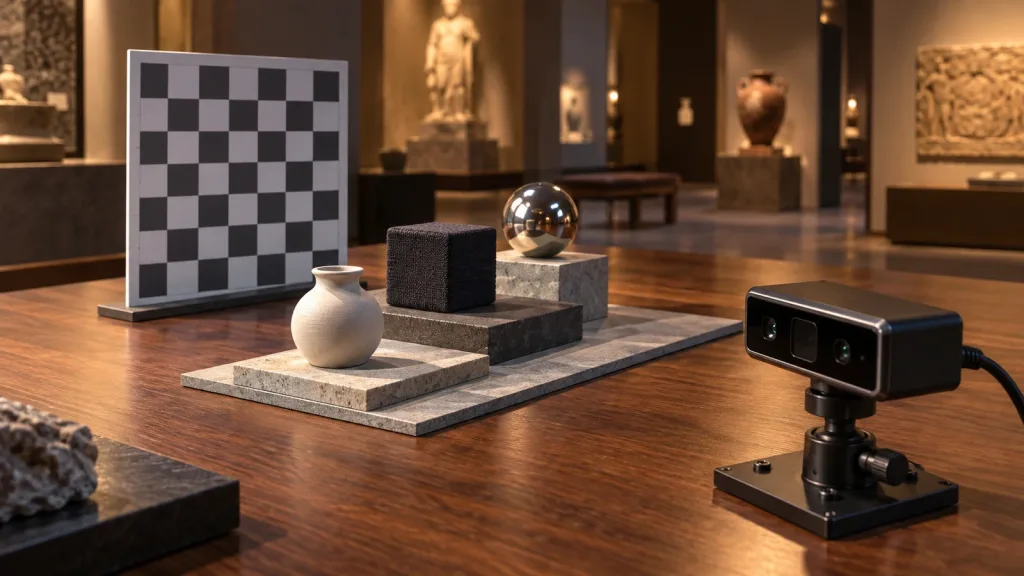
NIST's April 27, 2026 publication Bootstrap Metric for Quantifying the Depth Resolution of 3D Sensors is useful here because it defines depth resolution as the smallest physical depth change that creates a detectable change in the measured depth, and it ties that ability to sensor noise on the target. In practical buyer language, that means a single range headline is not the decision. The real question is whether the module still separates the pallet edge, cart leg, shrink wrap, or fixture lip that your robot must react to.
The 2026 paper Environment-Adaptive Solid-State LiDAR-Inertial Odometry adds the second warning. Solid-state LiDAR can be fast and lightweight, but mapping and localization can still degrade in geometrically weak or perceptually degraded environments. That matters because a good-looking lab demo may hide the exact aisle geometry that causes drift or weak obstacle interpretation on the real robot.
Host handoff is the third proof gate. Nav2's current mapping and localization documentation shows that robot costmaps can use LaserScan and PointCloud2 inputs for obstacle and voxel layers. If your module cannot reach a stable first dataset, the rest of the stack discussion is premature. If your team is bridging robotics and UAV programs, ArduPilot's current rangefinder setup overview is also useful because it treats LiDAR and rangefinders as object-avoidance inputs and makes the configuration path explicit.
Decision chart for robotics validation
| Validation area | What to verify | Why it matters | Reject if |
|---|---|---|---|
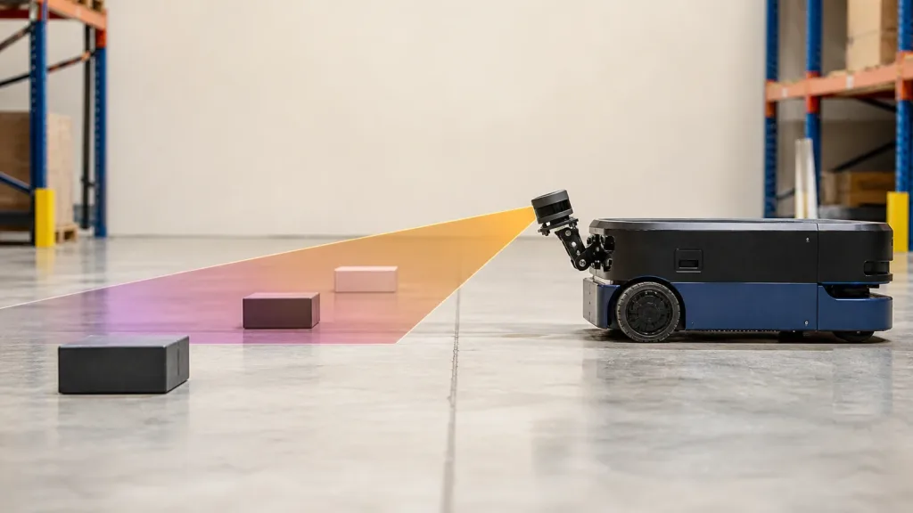
| Scene fit | Whether the FoV and mounting position actually cover the pallet edge, cart leg, rack upright, or other obstacle that matters | Robotics failures often come from geometry mismatch, not missing headline range | The test uses only a centered flat target with no real edge or thin-object check |
| Depth resolution realism | Whether the sensor separates the real depth changes your robot must notice on matte and reflective surfaces | Usable obstacle judgment depends on detectable depth changes, not on one max-distance number | The supplier cannot show weak-scene or mixed-material evidence |
| Degenerate geometry risk | How the sensor behaves in long aisles, low-detail walls, and partial-structure scenes | Compact solid-state LiDAR can still face mapping or localization weakness in poor geometry | The proof run avoids corridor, rack, or low-structure cases entirely |
| Host handoff | Which interface gets you to the first replayable dataset and whether the host accepts the data form you need | The best sensor can still stall a project if the first handoff path is wrong | The team cannot name the first logging path or the intended host message format |
| Replay evidence | Saved weak frames, scene notes, and a repeatable test position | Reviewable evidence is what turns a demo into an approval decision | The test result depends on one live run with no saved evidence |
Exact featured-product parameters to screen
The current Featured product for this workflow is the LiDAR Drone Module – MRP-LD1 Solid-State dToF Sensor. The product facts below come directly from the Featured WooCommerce export and form the factual baseline for this article.
| Parameter | Published value | Robotics buyer implication |
|---|---|---|
| Ranging principle | dTOF | Evaluate real depth behavior, not only a camera-like visualization. |
| Scanning principle | SPAD (Single-Photon Avalanche Diode) | Treat sensitivity language as a reason to test weak scenes, not a reason to skip them. |
| Emitter | 940nm VCSEL | Ambient light and surface behavior still belong in the acceptance run. |
| Laser safety | Class 1 (FDA Recognized Eye-Safe) | Useful for module screening while the final robot still needs a system-level safety review. |
| Range | Indoor 0.5-25m; outdoor 0.2-8m | Judge the module against the robot's real clearance and stop-decision band, not the far end alone. |
| Ambient-light resistance | 80Klux | Mixed lighting and reflective spill still need verification in your own environment. |
| Accuracy | 0.2-1m <= +/-3cm; 1-5m <= +/-5cm; 5-8m <= +/-10cm; 8-15m <= +/-20cm | Map each band to the robot's actual obstacle and stopping logic before you compare suppliers. |
| FoV | 60 degrees (H) x 45 degrees (V) | Project that cone onto the robot's real aisle geometry before calling coverage acceptable. |
| Resolution / frame rate | 40 x 30 at 10fps | Potentially workable for compact robot checks if the team defines what evidence counts as usable. |
| Interfaces | UART / UVC / UDP | Pick the fastest path to a stable replayable dataset first, then optimize the architecture. |
| Software support | Windows / ARM / Linux / Android | Useful when the bench logger and embedded host are different systems. |
| Power / weight | 5V, 1.2W, 8g | Helpful for compact robot mast placement and lightweight embedded deployments. |
Validation workflow before robot pilot approval
1. Define the exact obstacle decision the robot must make
Write the real scene down before the bench run starts. Is the robot deciding around pallet corners, thin cart legs, rack faces, reflective wrap, or floor-level fixtures? If the test scene does not include the same obstacle geometry, the proof is too soft.
2. Map the published FoV onto the real mounting geometry
For the MRP-LD1, the published FoV is 60 degrees (H) x 45 degrees (V). That number only becomes useful when the team projects it from the actual mounting height and offset on the robot. A compact front-corner installation can look fine in a centered screenshot while still missing the exact thin obstacle that causes a field failure.
3. Turn LiDAR for Robotics into a measurable acceptance test
Use the NIST depth-resolution idea as a practical check: can the module detect the depth differences that matter on your real target materials? A pallet edge, shrink wrap, matte carton face, and thin steel leg create a better approval scene than a single flat board. If the robot cannot separate those structures clearly enough for the task, the module is not ready for a pilot just because the max range looks attractive.
4. Capture weak scenes and replay them
The MRP-LD1 supports UART, UVC, and UDP. Start with the interface that gets you to a saved dataset fastest. If the team needs a refresher on host choices, use UART, UVC, or UDP, the documentation hub, and the sample datasets before the pilot expands.
5. Verify host handoff before the robot pilot grows
If the stack is ROS-based, define whether the first acceptance path should become LaserScan, PointCloud2, or another intermediate representation for review. If the program also touches UAV autonomy, define whether the same module family will later feed a controller-side avoidance path. The important thing is to choose the first proof route deliberately instead of assuming the host problem will solve itself later.
Interface, data, and integration section
Nav2's current documentation is a useful benchmark because it shows obstacle and voxel layers using `LaserScan` and `PointCloud2` from a lidar source. That means your first question is not "does the robot use Nav2?" The first question is "what data form gets us to a replayable acceptance run with the fewest assumptions?" For some teams, that is UVC-based visual review. For others, it is a UART or UDP path that moves directly toward the embedded host.
| Integration topic | Questions to answer before approval |
|---|---|
| First host | Will the first proof run happen on Windows, Linux, ARM, or a mixed bench-to-embedded workflow? |
| First data form | Does the team need quick visual review, structured depth output, or a path toward `LaserScan` or `PointCloud2`? |
| Replay discipline | Can the team save the ambiguous frames and compare runs from the same scene setup? |
| Controller handoff | If this module family later feeds a robot or UAV avoidance stack, who owns that translation path and when will it be checked? |
| Failure ownership | If the run goes weak, can the team say whether the next action belongs to mechanics, optics, parsing, middleware, or vendor support? |
For broader troubleshooting, use common LiDAR integration issues and how to diagnose them, how to evaluate a LiDAR point cloud dataset before integration, and the earlier robotics mapping LiDAR guide if the discussion needs to move from pilot screening into a larger navigation program.
Realistic application case
Consider a compact warehouse inspection cart that must approach shrink-wrapped pallet corners without clipping thin steel utility carts parked nearby. The team wants a lightweight module rather than a heavier spinning lidar, and it expects the same module family to remain relevant for future robot and UAV perception work. On paper, the MRP-LD1 looks promising because it is compact, light, and offers `UART`, `UVC`, and `UDP` outputs. The wrong next step is to approve it from a single centered range demo.
- Mount the module at the real front-corner height and offset planned for the robot.
- Run one scene with the pallet corner only, one with thin steel legs only, and one with both obstacles in the same frame.
- Repeat the run under the same aisle lighting with the same stop-distance markers so the evidence is comparable.
- Save the output and verify that the host can replay the weak cases rather than relying on a live impression.
- Approve the pilot only if the team can explain coverage, depth behavior, and host handoff together.
This case is useful because it exposes the most common robotics buying error: approving a compact depth module from a clean obstacle instead of from the actual obstacle mix the robot must judge in production.
Common mistakes
- Treating maximum range as the decision instead of checking real depth separation on the robot's actual scene.
- Ignoring how a small solid-state FoV maps onto front-corner mounting geometry.
- Using only flat centered targets and skipping pallet edges, legs, or reflective wrap.
- Delaying host-path validation until after the sensor has already been approved.
- Assuming a good bench demo guarantees stable behavior in geometrically weak aisles or low-detail corridors.
- Approving the module from one live run with no saved replay evidence.
RFQ and evaluation checklist
| Checklist item | Why it belongs in the approval sheet |
|---|---|
| Real mounting position and offset | Keeps the proof tied to the actual robot geometry rather than a generic bench stand. |
| Mixed obstacle set | Forces the test to include edges, thin structures, and reflective surfaces that expose weak behavior. |
| Depth-separation note | Makes the team define what physical depth change must be detectable for the task. |
| Preferred first interface | Reduces time to the first stable replayable dataset. |
| Host message target | Clarifies whether the acceptance run aims toward visual review, `LaserScan`, `PointCloud2`, or another path. |
| Saved weak-scene evidence | Makes the approval auditable across engineering, software, and purchasing teams. |
| Escalation owner | Prevents ambiguity when a failure belongs to mechanics, optics, middleware, or vendor follow-up. |
Approve the robot scene, not the headline spec
A compact solid-state dToF LiDAR can be a strong robotics fit when the team validates the real obstacle geometry, the actual depth separation that matters, and the first host handoff before the pilot grows. That is how a buyer turns a sensor shortlist into a defensible approval decision.
- Start from the Featured product, the true mounting geometry, and the weakest obstacle mix you expect the robot to face.
- Use product documentation, datasets, and interface planning to convert the first bench run into replayable evidence.
Purpleriver, founded in 2015, develops solid-state dToF LiDAR technology and provides product, documentation, and dataset resources that can support a structured robotics evaluation workflow around the MRP-LD1 module.
Contact Purpleriver with your robot geometry, obstacle set, and host path so the next discussion starts from test evidence instead of assumptions.