Quick answer: A miniature LiDAR sensor becomes a credible design candidate only after five checks agree: installed payload and power, mounted coverage, usable data path, representative-scene behavior, and system ownership. Published module specifications can qualify a bench evaluation; they cannot approve a mechanical design or a vehicle behavior by themselves.
Do not let “miniature” become a mounting decision
An integration team often receives a compact depth module just as enclosure and bracket work is starting. That timing makes a small published mass tempting: put the sensor in the CAD model, route a cable, and solve the rest during flight or field tests. It is safer to stop one step earlier. The word miniature tells you little about the finished assembly’s envelope, fastening, cable bend, optical window, cooling path, vibration exposure, or center-of-gravity effect.
Use a miniature LiDAR sensor as a candidate only when its published facts match the intended role and the unlisted facts have a named owner. The MRP-LD1, for example, is listed as an 8 g, 1.2 W, 5 V solid-state SPAD dToF module with depth and point-cloud output. That is enough to plan a sample evaluation—not enough to assume a bracket, connector arrangement, host parser, or complete avoidance behavior.
This article is for the engineer or technical buyer deciding whether to spend the next design cycle on a compact depth module. It deliberately separates a sensor stream from the host processor, perception logic, planning, flight controller, and validated response. For a broader process, start with the site’s compact dToF evaluation workflow.
Miniature LiDAR sensor: the five-gate screen
| Gate | Decision question | Evidence before a mount release | Stop condition |
|---|---|---|---|
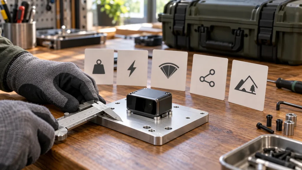
| 1. Installed payload and power | Can the finished assembly fit the real payload and power budgets? | Scale the module, fixture, cable, connector, protection and regulator; capture supply behavior at startup and streaming. | Only the bare-module values fit, or the rail is not verified. |
| 2. Mounted coverage | Does the final viewing volume cover the direction, distance and target geometry that matter? | Body-frame drawing plus a physical occlusion survey at the proposed angle. | Airframe, window, landing gear or bracket blocks a required sector. |
| 3. Data-path ownership | Can the chosen host receive, validate, timestamp and recover the output? | Recorded raw samples, parser/replay test, stale-data rule and fault-recovery result. | No owner for format conversion, invalid-data handling or health monitoring. |
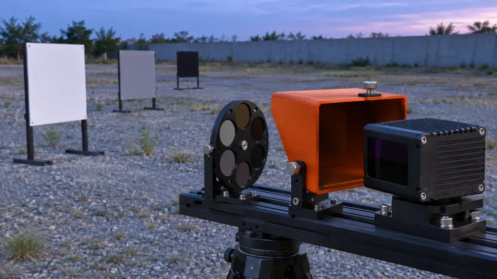
| 4. Representative scene | Does the proposed use case pass a defined target/light/distance matrix? | Repeated runs with the actual surface finishes, angles, movement and illumination. | One attractive demonstration stands in for the full matrix. |
| 5. System boundary | What exactly happens after a valid depth result reaches the host? | Documented interface from sensor output through perception and decision logic to an observed response. | The module is described as the complete safety or avoidance system. |
NIST’s methods for evaluating 3D LiDARs are a useful reminder to state conditions and measurements rather than treating a data sheet as a deployment result. This does not transfer any NIST result to a compact module; it informs the discipline of the test plan.
What to lock before the first bracket drawing
Write the role in one sentence: for example, “provide forward near-field depth data to a companion computer for a defined inspection-route experiment.” Then list the required direction, target types, closest and farthest relevant distances, vehicle or robot motion, lighting, host platform, available ports, power rail, retained logs, and what a failed measurement must cause downstream. If any item is unknown, label it unknown rather than hiding it inside a generic “obstacle avoidance” requirement.
MRP-LD1: use the published baseline, then list what is still unknown
The Featured MRP-LD1 Drone LiDAR Sensor product baseline can anchor a compact-module screen. These are published module facts, not system-level promises.
| Published field | MRP-LD1 value | How to use it in the screen |
|---|---|---|
| Principle and emitter | Solid-state SPAD direct time of flight (dToF); 940 nm VCSEL | Identify the sensing approach, then test it in the intended scene rather than inferring system performance. |
| Mass, supply and power | 8 g; 5 V; 1.2 W | Start a total installed budget; do not omit mount, cable, protection, regulation or host cost. |
| Field of view and output | 60° horizontal × 45° vertical; 40 × 30; 10 fps | Map the mounted rectangular coverage and decide which pixels, sectors or conditions the host must accept or reject. |
| Published ranging baselines | 0.5–25 m indoors; 0.2–8 m outdoors | Keep indoor and outdoor tests separate and validate the actual target, light, angle and motion. |
| Ambient-light baseline | 80 Klux | Include bright-scene conditions in the evidence matrix; it is not a substitute for the matrix. |
| Outputs and interfaces | Depth and point cloud; UART, UVC and UDP | Select the transport that the target host can capture, validate and replay. |
| Software support | Windows, ARM, Linux and Android | Confirm the required operating environment and supplied resources on the actual target platform. |
| Listed applications | Robot navigation and obstacle avoidance; UAV obstacle avoidance and altitude hold; AR/VR auxiliary focusing; industrial inspection and security | Use an application label to frame a test—not as proof that the finished system is approved for that use. |
Before releasing the mount, request the current mechanical drawing, mounting information, connector and pinout material, protocol revision, sample data, and the information needed to exercise the chosen interface. Those items are not supplied by the published baseline above, so the article does not invent them.
A realistic pilot: compact inspection cart at a rack end
Scenario—an evaluation plan, not a customer result
Consider a compact indoor inspection cart that must identify the end of a storage rack before a slow approach. Its integration lead has an ARM/Linux host, a 5 V rail, a limited payload allowance, and a forward sensor location. The MRP-LD1’s published 8 g, 5 V, 1.2 W, 60° × 45° field of view and ARM/Linux support make it a plausible bench candidate. They do not show whether the final cart can respond correctly.
The team makes a blank mounting plate, records the finished assembly’s mass, and scans for bracket and bumper occlusions. It then captures depth and point-cloud output across a target board containing matte dark, light painted and brushed-metal panels at several angles and approach distances. At each condition, it logs whether data arrives, how the host marks invalid or stale data, and whether the proposed decision zone remains covered. A negative result triggers a design change or rejects the candidate; it is not averaged away.
This scenario works because the proof artifact matches the next design decision: the team needs a mount-ready coverage and data-handling answer, not a generic claim that a small sensor can avoid obstacles. The site’s LiDAR sensor validation guide offers a related way to retain pilot evidence.
Prove the data handoff before you promise a behavior
Depth output is not automatically a controller command. Decide whether the host will work with raw depth pixels, a point cloud, a range estimate, or a derived sector representation. For each option, define units, coordinate frame, timestamp source, invalid-data representation, maximum age, transport failure behavior, and the log needed to reproduce a decision. The sensor-to-flight-controller data-contract guide is a useful companion for assigning those responsibilities.
UART, UVC and UDP are documented MRP-LD1 interfaces, but none of their names removes integration work. With UART, retain the actual protocol revision and parse result. With UVC, retain negotiated format and recorded samples. With UDP, retain addressing and loss/recovery observations. In every case, replay a captured data set after a host restart and simulate stale, missing and invalid samples. The aim is to prove what the host does when the stream is imperfect.
For vehicle projects, keep the sensing test separate from configured behavior. The official ArduPilot simple object avoidance documentation describes configured proximity-sensor approaches; it does not establish compatibility or safety performance for this module. A vehicle team must still validate its own sensor conversion, orientation, controller configuration and response in its intended operation.
Common mistakes that make a compact-sensor pilot misleading
- Equating module mass with installed mass: add every bracket, cable, regulator, enclosure and protection component.
- Drawing a cone instead of testing a volume: check the final mount, target angles and nearby occlusions.
- Using one wall as the whole scene: use representative material, illumination, distance and motion cells.
- Approving an interface from a device enumeration: retain parsed data, timestamp behavior, health checks and recovery evidence.
- Calling a depth module a finished avoidance system: name the host, perception, planning, controller and verified response separately.
- Waiting until flight or field testing to define pass/fail: freeze the acceptance matrix before reviewing the sample.
RFQ and evaluation checklist
- State the platform, use case, indoor/outdoor scene, working-distance window and target materials.
- State the chosen host system, preferred interface and retained log format.
- Provide available voltage, payload allowance and the complete installed-mass target.
- Ask for the current mechanical, interface, protocol and sample-data materials needed for a bench assessment.
- List the target mounting direction and any expected window, vibration, dust or motion constraints.
- Define the acceptance matrix: target, angle, distance, illumination, motion, repeat count and owner.
- Ask for an evaluation sample or project-specific quote only after the evidence package is defined.
For another selection perspective, compare this engineering screen with the site’s data-evidence buying guide for compact dToF modules.