Integration evidence for embedded perception teams
dToF LiDAR FAQ: Evidence to Request Before a Depth-Module Evaluation
Quick answer: A useful dToF LiDAR evaluation begins with a bounded scene, an inspectable depth/point-cloud output, and a host handoff you can repeat. Ask for the module’s documented output, interface, field of view, frame rate, power and environmental baseline; then test those facts with your target, mounting, light and motion. Do not treat a compact depth module as a complete navigation, safety or flight-control system.
What does dToF LiDAR actually measure?
Direct time-of-flight (dToF) depth sensing estimates distance from the travel time of emitted and returned light. A technical review of SPAD-based dToF architectures describes the timing-and-detection chain and why background light can reduce signal-to-background conditions in a real scene. Read the peer-reviewed dToF sensor-architecture analysis.
That principle is useful, but it does not turn a module into a finished application. A usable result still depends on the target surface and geometry, illumination, mounting, movement, the host’s handling of the data, and the response logic that an integrator builds around it. For a practical vocabulary refresher, see these drone LiDAR terms for field of view, frame rate and point clouds.
dToF LiDAR FAQ: which evidence matters before an integration decision?
Start with two questions that separate a documented component from an assumed system outcome: What does the module explicitly provide? and what must our team prove in our own scene? The second question matters because SPAD/dToF acquisition behavior is affected by the complete signal chain and background conditions; a statistical treatment of SPAD time-of-flight acquisition explains the role of repeated photon returns, timing information and background light. See the peer-reviewed SPAD time-of-flight modelling paper.
| Question | Evidence to collect | Decision it supports |
|---|---|---|
| What is the intended sensing task? | A short scene card: target type, distance band, indoor/outdoor condition, motion and mount location. | Whether the evaluation has a defined boundary rather than a demo-only goal. |
| What data is available to the host? | One retained sample, its format, timestamp or capture index, units and coordinate-frame note. | Whether the receiving software team can inspect and reproduce the handoff. |
| How will the sensor reach the host? | The documented interface, connector/power plan and a first-stream acceptance record. | Whether electrical, software and ownership questions are visible early. |
| What conditions change the result? | Runs that deliberately vary target material, angle, ambient light, mounting and motion. | Which condition needs more engineering before any product-level claim. |
Screen documented module facts before promising an outcome
The following facts are the supplied WooCommerce record for the MRP-LD1 Drone LiDAR Sensor. They are a screening baseline, not a promise that a particular robot, UAV or AR/VR design will achieve a specific outcome.
| Documented item | MRP-LD1 exported fact | Evaluation question |
|---|---|---|
| Ranging / sensing principle | dToF (direct time-of-flight) with SPAD scanning principle; 940 nm VCSEL | Does the prototype plan identify the measured scene and the conditions to validate? |
| Data | Real-time depth images and 3D point-cloud data; 40 × 30 resolution; 10 fps | Can the host retain and label a first sample before downstream logic is tuned? |
| Interfaces | UART, UVC and UDP; software support listed for Windows, ARM, Linux and Android | Which documented path will own the first stream and logging? |
| Optics / envelope | 60° (H) × 45° (V) field of view; 8 g; 1.2 W; 5 V supply | Does the proposed mount preserve the required field and the platform’s power budget? |
| Published environmental baselines | 0.5–25 m indoors; 0.2–8 m outdoors; up to 80 Klux ambient-light resistance; −20 to 60 °C operating temperature | Which target, light, angle and motion cases must the team validate for its own deployment? |
| Safety classification | Class 1 (FDA Recognized Eye-Safe) in the supplied product record | What project-specific safety review remains necessary for the complete system? |
If the discussion is still at the component-selection stage, pair this table with the site’s evaluation-sample checklist. It keeps the conversation on documented facts instead of inferred range, accuracy or control behavior.
Build a bounded scene plan before running a demo
Write the first scene plan on one page. Name the object or surface, its placement, the distance band you intend to exercise, ambient-light condition, sensor orientation, platform state and the thing that will be retained after the run. This is not a universal test protocol; it is a way to make the team’s first comparison honest and repeatable.
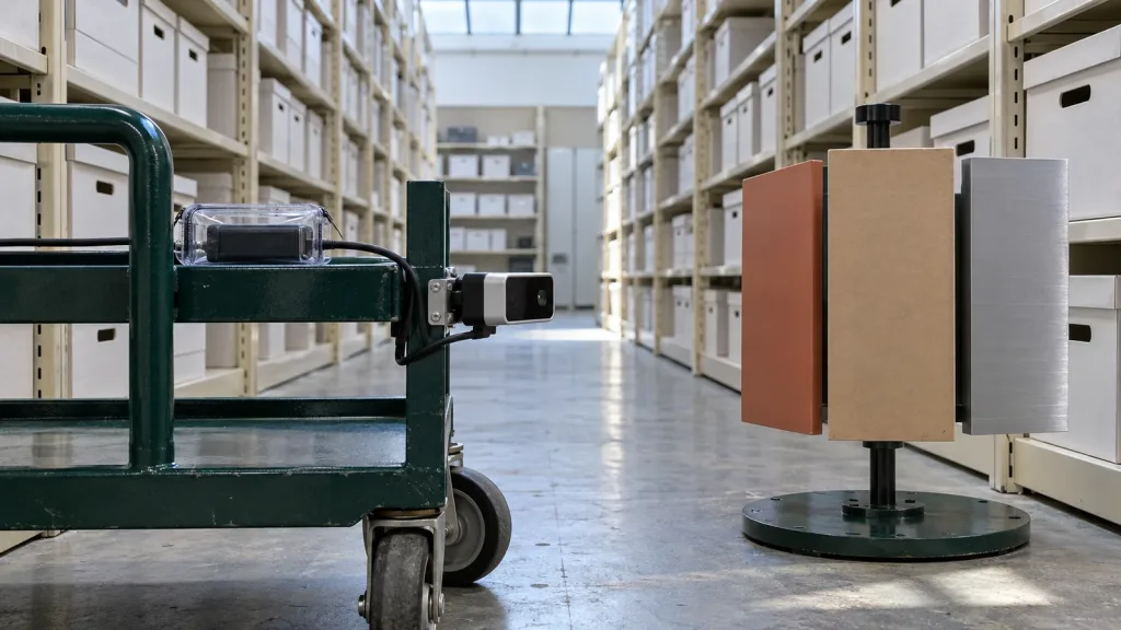
For example, a team evaluating a compact sensor for an indoor mobile platform might use a matte tote, a dark fabric edge and a reflective label as separate targets. The goal is not to claim that the cart can navigate autonomously. The goal is to observe whether the documented depth/point-cloud handoff is present under the particular target and mounting conditions the team expects to face.
Keep the result connected to raw evidence. The guides to visualizing dToF depth data during early testing and evaluating a LiDAR point-cloud dataset before integration can help a reviewer distinguish an inspectable sample from a persuasive screenshot.
Make the data and interface handoff reviewable
A module evaluation slows down when electrical ownership and data ownership are left implicit. Choose one documented interface for the first connection, name the host and log where the first data is stored. The module’s supplied record lists UART, UVC and UDP, but interface selection is a host-integration decision—not evidence that every path is already implemented in your application. Use this comparison of UART, UVC and UDP for LiDAR integration to frame the handoff discussion.
For each retained sample, attach a compact record: capture date/time, sensor and firmware identifiers if available from your own setup, interface used, host environment, scene card, units, coordinate-frame convention, and a note of any conversion. If a team generates a display image or filtered cloud, keep it alongside—not instead of—the source received by the host. That makes later mapping, visualization or diagnosis less dependent on memory. For broader troubleshooting context, see common LiDAR integration issues and how to diagnose them.
Case: a compact depth-module feasibility review for a service cart
Imagine a facilities team assessing a small service cart in a controlled indoor aisle. The first milestone is deliberately narrow: capture the MRP-LD1’s documented depth/point-cloud output at the host while the cart is stationary, then repeat with the same three target materials at a planned distance and mounting angle. The team stores the scene card, the source sample and the interface note for each run.
Only after that review can the team decide whether to enlarge the scene, add motion, involve its perception stack or create a response test. No single sample establishes navigation reliability, obstacle avoidance, braking, coverage or safety. The value of the first run is a shared evidence package that lets electrical, software and systems reviewers ask the next question from the same record.
Common dToF LiDAR evaluation mistakes
- Calling a depth stream a finished system. Treat the module, host processing, planning and control response as separate responsibilities.
- Testing one cooperative target. Plan target material, angle and lighting variations that resemble the intended scene.
- Saving only screenshots. Retain the source output and the scene/interface notes needed to interpret it.
- Assuming a published baseline transfers unchanged. Use indoor/outdoor range and ambient-light figures as documented screening facts, then validate the real scene.
- Choosing an interface after the mechanical build. Assign a host and logging owner while the mount and power plan are still easy to change.
- Turning an early demonstration into an accuracy or safety claim. Report what the team observed, the exact conditions, and what remains untested.
RFQ and evaluation checklist
- State the platform, application and the first bounded sensing task.
- Describe target materials, working-distance band, indoor/outdoor light and expected motion.
- Name the proposed mount location, field-of-view constraints, power source and thermal environment.
- Choose the first host and one documented interface to evaluate.
- Ask for the relevant product documents, SDK resources and sample data.
- Define the source data to retain, the scene card and the reviewer who will accept the handoff.
- List the result that would justify a next-stage prototype—and the outcomes this first evaluation cannot prove.
Turn the FAQ into an evaluation brief
Preparing a compact evidence brief before requesting a sample makes technical discussions faster and clearer. Share the platform, scene, distance band, host, preferred interface, sample quantity and project timing so the next conversation can stay grounded in the intended integration.