Downward sensing becomes a flight-critical integration question as soon as a UAV team wants a compact depth source to inform low-altitude behavior. A promising bench stream is not yet a usable ground reference. The team still has to prove the installed viewing geometry, the physical scenes it can observe, the meaning and age of the data delivered to the host, and the response when that data becomes stale.
This guide is for UAV systems engineers and technical buyers evaluating a compact dToF depth module before a prototype uses its data in an altitude-hold, landing, terrain-relative, or near-ground workflow. It is deliberately a validation guide, not a claim that one module completes flight control or obstacle avoidance.
| Quick answer | Validate downward sensing as a chain: installed sensor view → representative ground evidence → documented output interpretation → tested host/controller handoff → defined stale-data behavior. |
|---|---|
| Do not assume | Nominal range, a clean indoor preview, or an interface name proves native autopilot compatibility, low-altitude control performance, or a safety function. |
| First decision | Keep the source as an evaluation input until the complete aircraft, sensor mount, host conversion, and flight-controller configuration pass a project-defined test plan. |
Downward Sensing Is a Ground-Reference Handoff, Not a Box to Tick
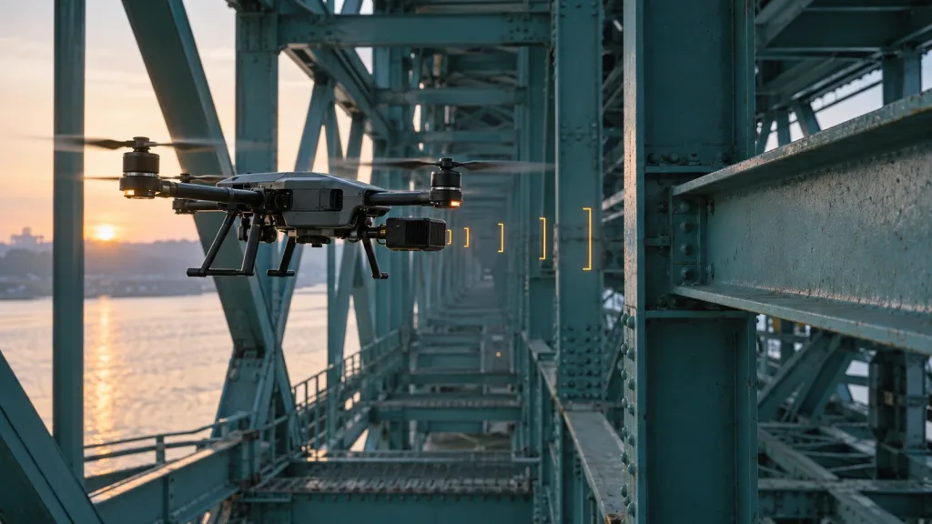
A downward-facing source can contribute useful distance information in low-altitude UAV work, but its role depends on the full system. The official PX4 distance-sensor guide describes uses such as terrain following, terrain holding, landing behavior, and collision prevention, then separates setup and testing from the sensor list. That distinction matters: a supported use case in an autopilot ecosystem is not proof that every depth module, data converter, mounting angle, or scene behaves the same way.
For an evaluation module, draw the chain before configuring a flight mode: optical center and downward axis; actual ground/target scene; raw depth or point data; host-side parsing and any range reduction; timestamp and validity rules; controller-facing message or driver; then the vehicle response and fallback path. A break at any stage makes the final “altitude input” untrustworthy even when the original sensor stream looks plausible.
Purpleriver’s earlier downward vision system validation guide is useful background for low-altitude scenarios. This article narrows the question to the evidence a team should retain before calling a downward sensor stream a tested ground-reference handoff.
Decision Table: What Must Be Proven Before a Low-Altitude Handoff
| Gate | What to record | Why it matters | Do not proceed when |
|---|---|---|---|
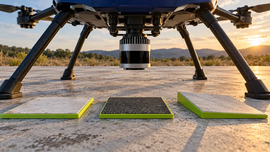
| Installed view | Optical-center location, downward axis, airframe/landing-gear occlusion, window condition, and field-of-view sketch | The physical aircraft—not a bench fixture—defines what the source can see. | The planned ground zone has unmeasured blind areas. |
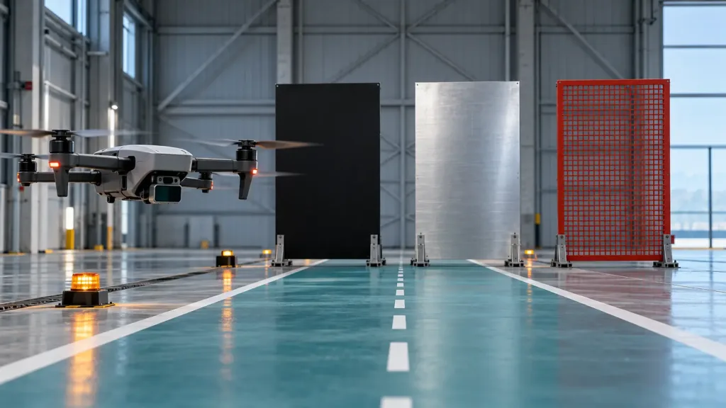
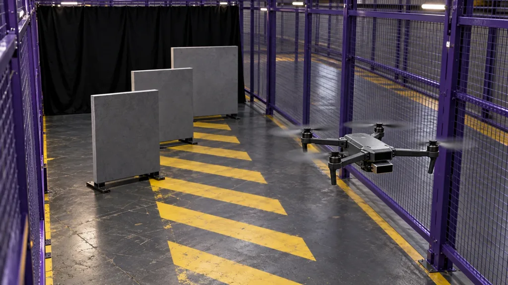
| Representative ground evidence | Runs over the actual ground materials, slope transitions, height steps, lighting directions, and rotor-wash conditions relevant to the project | A flat matte floor cannot stand in for every operating scene. | Returns are accepted only from a convenient indoor surface. |
| Source validity | Data units, invalid-value rule, confidence handling if available, sample age, dropouts, and restart behavior | A controller needs to distinguish a current value from a stale or invalid one. | The host cannot state what a missing or old observation means. |
| Handoff contract | Selected UART/UVC/UDP path, host conversion, orientation, timestamp, minimum/maximum limits, and logged output | The integration boundary is where otherwise-good data is often misinterpreted. | The interface is named but no measurable input contract exists. |
| Vehicle response | Project-defined use, fallback, alert, and test evidence for the actual controller configuration | A distance source is not itself a complete control or safety system. | Response assumptions have not been exercised under controlled conditions. |
Exact Featured-Product Parameters to Screen First
The current WooCommerce Featured product is the MRP-LD1 Drone LiDAR Sensor. Its exported facts make it a candidate for evaluation; they do not establish a native PX4/ArduPilot driver, a MAVLink implementation, an end-to-end control latency, or a complete UAV safety function.
| Published parameter | MRP-LD1 value | Evaluation question |
|---|---|---|
| Mass and power | 8 g; 1.2 W; 5 V supply | Can the final aircraft accommodate the module, mount, cable, protection, and power-quality needs? |
| Ranging principle | Solid-state dToF with SPAD scanning; 940 nm VCSEL | What ground materials, angles, windows, and ambient-light conditions should be included in the physical test matrix? |
| Published ranging baseline | 0.5–25 m indoors; 0.2–8 m outdoors | What conservative project-specific tested envelope is actually acceptable after mounting and host processing? |
| Field of view and output | 60° × 45°; 40 × 30 resolution; 10 fps; depth and point-cloud output | Where do the installed view and usable ground sample fall, and what output reduction is documented? |
| Interfaces | UART, UVC, UDP; Windows, ARM, Linux, Android support | Which host path will parse, validate, timestamp, log, and deliver the evaluated output? |
| Environmental baseline | 80 Klux ambient-light resistance; operating −20°C to 60°C | Which aircraft-level tests remain necessary for the actual site, window, vibration, thermal load, and light direction? |
The listing also gives accuracy bands by range. Treat those values as published module specifications, not as a promise of installed aircraft performance. Target reflectivity, angle, airframe vibration, optical window condition, ground geometry, ambient light, parsing, and controller configuration still require validation.
Build a Ground-Reference Validation Lane Before Flight
Start with a restrained, ground-based test setup using the real aircraft, final proposed mount, cable routing, power source, and host processor. Mark the sensor’s optical-center axis and make the data log traceable to each run. Do not tune a flight mode first; capture the source evidence before filters or response logic hide the cause of an unexpected value.
- Document the installed geometry. Measure the optical-center position and downward orientation relative to the airframe, landing gear, ground plane, and any window. Photograph known self-occlusions.
- Choose physical ground references. Use project-relevant flat, textured, dark, light, sloped, and stepped surfaces. Do not generalize a single material result to another site.
- Sweep height and attitude. At controlled, documented heights and small attitude changes, log raw output, valid/invalid state, host receipt time, and any converted range.
- Introduce realistic disturbances. Include transition edges, sun direction where relevant, vibration representative of the installation, and intentional source interruption. Establish the project’s response rule before free-flight testing.
- Freeze a versioned baseline. Retain hardware, window, bracket, firmware, host build, parsing rule, controller configuration, and a short raw dataset with the evaluation report.
For low-altitude use, the relevant question is rarely “does it measure something?” It is “does the retained evidence show that the exact installed chain makes a current, correctly interpreted observation across the project’s declared envelope?” The site’s drone altitude-hold LiDAR validation guide provides adjacent evaluation context; keep the final flight-response decision with the responsible system owner.
Interface, Data, and Flight-Controller Handoff
MRP-LD1 lists UART, UVC, and UDP. That tells an evaluation team which transport families may be available; it does not say that the module emits a specific autopilot protocol. Select a host path, obtain the current protocol/documentation, and state exactly how a host converts or exposes the evaluated data. The related UART, UVC, or UDP guide can help frame the transport choice.
If a project deliberately produces a MAVLink distance-sensor handoff, the official MAVLink DISTANCE_SENSOR definition is a useful contract checklist: it defines timestamp, minimum, maximum, and current distance, device ID, and orientation fields. Record the conversion owner, source units, orientation convention, timestamp origin, rate, validity policy, clipping rule, and what occurs when a frame is missing. Do not label an output “MAVLink compatible” unless the integrated system actually implements and tests that contract.
For controller behavior, document the actual firmware and configuration rather than relying on a blog formula. The official ArduPilot rangefinder guidance notes that downward-facing rangefinders can be used in height-control modes and warns that the configured maximum must be tested and appropriate. That is an integration lesson, not a declaration that the MRP-LD1 is an ArduPilot-supported rangefinder. Keep the product stream, host conversion, and controller configuration as separate acceptance items. The site’s flight-controller data-contract article offers a practical way to organize that evidence.
Illustrative Case: A Ground Transition Is Not a Sensor Specification
Illustrative engineering scenario—not customer results: a UAV team mounts a compact dToF module beneath a multicopter and wants to assess whether it can contribute a ground-reference input during a low-altitude prototype. The team first confirms the landing skids do not mask the intended downward view, then logs depth output over a flat pale pad, a dark textured mat, a shallow ramp, and a raised seam.
The first indoor run looks stable over the pale pad. On the ramp transition, the host-side rule that reduces spatial data to one range candidate becomes the central question: which points are valid, how is the ground region selected, what timestamp belongs to the output, and when does the host declare the source stale? The team records those choices, intentionally stops the stream on the restrained rig, and verifies the project-defined fallback or alert—not a claimed universal flight behavior.
Only after the mount, raw evidence, host transformation, controller configuration, and failure response are reviewed together does the team decide whether a controlled flight test is appropriate. This produces an evidence chain rather than a promise that a published range figure automatically yields reliable terrain following or landing.
Common Downward-Sensing Mistakes
- Calling a clean preview a flight input. Preserve raw data and prove the host/controller handoff separately.
- Using maximum range as an approved operating height. The tested, installed project envelope is what matters.
- Measuring from the housing edge. Use the optical center and true installed orientation.
- Ignoring skids, props, cables, and windows. The aircraft can create occlusion or contamination not present on a bench.
- Assuming an interface name proves autopilot support. UART, UVC, and UDP still require a defined, testable data contract.
- Discarding timestamps. A repeated old value can look plausible while the current ground state is unknown.
- Hiding invalid data with a filter. Log invalidity, dropouts, and recovery before choosing smoothing or fallback rules.
- Equating perception with a safety function. Keep sensing evaluation separate from the complete aircraft risk and control architecture.
RFQ and Evaluation-Sample Checklist
When requesting an evaluation sample or technical discussion, send the real test question rather than only asking whether a sensor supports downward sensing.
- aircraft type, proposed optical-center position, orientation, landing gear, enclosure window, cable path, power source, and mass budget;
- target ground materials, minimum/maximum project distances, slope/step geometry, lighting, vibration, temperature, moisture, dust, and expected motion;
- required output representation, source units, validity/confidence needs, timestamp semantics, stale-data behavior, log format, and retention period;
- selected UART/UVC/UDP path, host OS/hardware, current SDK/protocol/firmware questions, and any intended controller-side conversion;
- the actual autopilot and firmware, intended mode, declared tested maximum, fallback rule, and controlled-test owners;
- published product values to compare—rather than presume—against the aircraft-level acceptance plan; and
- evidence needed for approval: photographs of the mount, raw records, conversion settings, controller configuration, interruptions, and regression cases.
For navigation planning that goes beyond the downward path, keep the source coverage separate from the vehicle’s response margin; the obstacle-distance and brake-margin guide explains why sensing evidence alone is not a stopping-distance promise.
Plan the Ground-Reference Test Before You Freeze the UAV Design
Share your intended mount, ground materials, working-height envelope, lighting, host platform, preferred interface, and the evidence your flight-control team needs. Purpleriver can help compare those requirements with the MRP-LD1’s published parameters and prepare questions for an evaluation sample.