Custom LiDAR module projects go wrong when the request starts with a component and ends with an undefined station decision. An automation team may know it needs “3D sensing,” but still be unable to say what must be visible, which condition produces a usable event, who owns the data, or how a failed cycle will be reviewed.
For a compact fixture-cell pilot, write the data contract before requesting hardware. It keeps the mechanical, controls, and QA teams aligned—and gives a supplier enough context to discuss fit without turning a data sheet into an unproven station claim.
| Quick answer | Define one station decision, the physical zone that supports it, representative surfaces, a retained evidence record, and the host-side handoff before comparing custom LiDAR module options. |
|---|---|
| Best use | Automation teams evaluating compact depth sensing for a fixture, clearance, presence, or coarse-geometry pilot—not a promised production result. |
| Decision rule | Do not request a “custom” module until the team can draw the must-see zone and describe the event, evidence, and fallback in one page. |
Custom LiDAR module planning starts with the decision, not the sensor
The useful first sentence is not “we need a LiDAR.” It is a station decision such as: “Before the next carrier enters, determine whether the locator nest and exit lane are clear enough for the cycle to continue.” That sentence gives the team something a compact 3D sensor can be evaluated against. It also prevents a pilot from drifting into a vague visual demo.
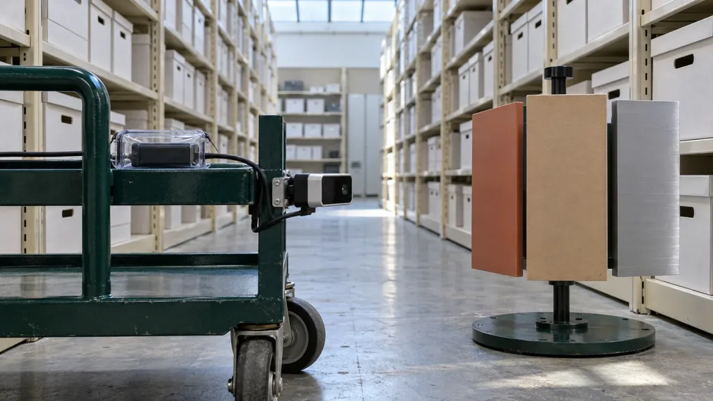
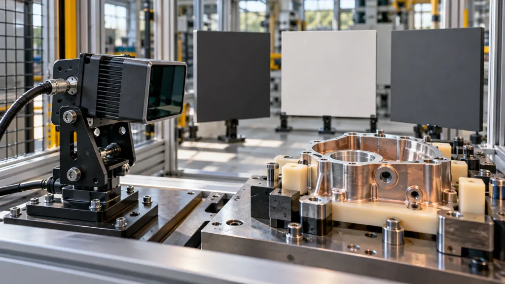
Next, draw the decision zone from the proposed mounting position. Mark the must-see edges, the allowed occlusions, the closest and farthest expected surfaces, and every bracket or fixture wall that might hide a feature. Then list representative part finishes and viewing angles. This is not needless paperwork: a published lidar study found that the returned waveform in its flash-lidar system was affected by travel distance, incidence angle, and surface material. That result is not a specification for a different module, but it is a sound reason to test the actual surfaces and geometry that the cell will use.
For general sequencing before the pilot, see Purpleriver’s compact dToF evaluation workflow. The focus here is narrower: the document that lets the supplier, integrator, and line owner agree on what one module evaluation must prove.
Decision chart: is the request ready for a custom-module conversation?
| Question | Ready answer | What to do if it is missing |
|---|---|---|
| What station decision is needed? | A single, observable pass / hold / review decision. | Write the decision before selecting a sensing method. |
| Which physical zone supports it? | A sketch of the must-see surfaces, distance envelope, and likely occlusions. | Measure the station and mock up the mount. |
| What can change at the target? | Known material, color, finish, orientation, and motion variations. | Gather representative parts or samples before a demo. |
| What does the host need? | A named data form, timing expectation, and evidence-retention path. | Choose a bench interface and logging owner. |
| What happens on uncertainty? | A defined hold, review, or fallback state owned by the station team. | Do not call the pilot production-ready yet. |
A module can be compact and still require a system decision above it. The sensor, mount, cable path, host parser, control logic, and line procedure each have a separate owner. Stating those boundaries early is more valuable than adding speculative performance requirements.
Published MRP-LD1 parameters: a baseline to validate, not a fixture-cell guarantee
The current WooCommerce Featured product is the MRP-LD1 Drone LiDAR Sensor. Its published parameters can help screen an early evaluation. They do not prove that any particular fixture, material, PLC, or safety workflow will work; validate the intended scene and host integration in the pilot.
| Published parameter | MRP-LD1 value | Planning implication |
|---|---|---|
| Ranging principle / scanning | dToF / SPAD | Plan an evaluation around depth-oriented data, not an assumed binary station result. |
| Wavelength / laser safety | 940 nm VCSEL / Class 1 | Record the optical and integration context for the intended station. |
| Listed range | 0.5–25 m indoor; 0.2–8 m outdoor | Use the station’s real distance envelope rather than a headline figure. |
| Ambient-light resistance | 80 klux | Include the real lighting condition in the evaluation record. |
| Field of view | 60° × 45° | Overlay the field on the mount sketch and inspect fixture-created blind zones. |
| Resolution / frame rate | 40 × 30 / 10 fps | Confirm that the zone and event definition fit the available spatial and temporal evidence. |
| Output | Depth images and 3D point-cloud data | Decide which output, if any, the host will retain for review. |
| Interfaces | UART / UVC / UDP | Choose the route that reduces pilot risk and supports replay. |
| Supply / consumption / weight | 5 V / 1.2 W / 8 g | Check the mechanical and electrical budget at the actual mount location. |
| Software support | Windows / ARM / Linux / Android | Name the bench and host environment in the request. |
The nine-field custom LiDAR module data contract
A data contract is a short agreement about what is measured, how it is labeled, where it goes, and what makes it useful. It is intentionally separate from a product specification. Use these nine fields in the sample request and pilot kickoff.
| Field | What to specify | Example of a usable answer |
|---|---|---|
| 1. Station decision | The event the station needs to make. | “Hold the cycle for review when the clearance zone cannot be evaluated.” |
| 2. Must-see zone | Physical surfaces, boundaries, and permitted blind areas. | A locator nest, exit lane, and the two edges that must remain visible. |
| 3. Target set | Representative materials, finishes, colors, and orientations. | Production-like parts plus the expected contaminated or worn variant. |
| 4. Mount reference | Position, orientation, mounting constraints, and window condition. | A bracket drawing with fixture posts and cable route marked. |
| 5. Operating conditions | Lighting, motion, vibration, temperature, and cycle condition to record. | Normal work lighting, part motion state, and any lamp state that changes during the cycle. |
| 6. Data handoff | Evaluation interface, host, parsed data form, and timestamp owner. | UVC to a bench host for replay during the pilot; final deployment path is still open. |
| 7. Decision evidence | What file or record explains a hold or unexpected event. | Saved source capture, mount revision, target label, and reviewer note. |
| 8. Acceptance rule | What must be repeatable before the next pilot stage. | Named target states are distinguishable in repeated trials under stated conditions. |
| 9. Fallback owner | What happens when the evidence is incomplete or contradictory. | The line owner routes the unit to review; the sensor is not treated as an automatic safety decision. |
Keep conditions with the evidence. Recent dToF research identifies effects of detector dead time, photon flux, pulse width, and time-of-flight quantization on ranging precision. Those findings do not assign a performance value to the MRP-LD1. They do explain why a test note should preserve its target, optical, and timing context instead of presenting one capture as a universal result.
Interface, data, and host handoff: choose the lowest-risk pilot path
Choose the evaluation interface for inspectability first, then decide whether it also fits deployment. A first pilot often needs a path that lets an engineer view, save, and replay data while the mechanical team adjusts the mount. That can be a more useful starting point than optimizing wiring before the pass/hold question is stable.
The MRP-LD1 lists UART, UVC, and UDP. Each is a documented product interface, not a promise of a particular software stack or factory protocol. In the request, name the host operating environment, which data representation the host needs, who parses it, where timestamps come from, and how a failed cycle can be reviewed. Purpleriver’s UART, UVC, or UDP interface guide is a useful companion for that choice.
Before committing engineering time, review the available documentation resources and sample datasets. If the project needs a point-cloud handoff, use the point-cloud dataset evaluation guide to agree on what a reviewable capture must contain.
Illustrative application case: locator-nest clearance before a carrier moves
Consider a cell where a carrier should move only after a machined housing has cleared a locator nest and a small exit lane. The team is not asking the module to provide precision dimensional metrology or to certify a safety function. It wants a disciplined pilot to learn whether a defined zone can be observed repeatably enough to support a line-review decision.
- The mechanical engineer draws the mount, nest, exit lane, and all bracket-created occlusions.
- The QA engineer supplies normal, reflective, darkened, and mis-seated representative parts.
- The controls engineer defines a hold-for-review state rather than an unexamined automatic reject.
- The integration engineer chooses the first capture interface and saves the target label, mount revision, lighting state, and raw evidence with each trial.
- The team approves a second phase only when the stated acceptance rule holds across the representative conditions.
That approach gives a supplier a concrete custom-module conversation: coverage, interfaces, constraints, and evidence are all visible. It avoids claiming that a compact sensor automatically solves the cell.
Common mistakes in a compact LiDAR pilot
- Calling “part present” the requirement when the real question is whether a particular edge, lane, or clearance volume is visible.
- Testing one clean, front-facing target and omitting the actual material, angle, or worn-condition variants.
- Using published range, resolution, or field of view as proof of station fit without a mount sketch.
- Assuming depth or point-cloud output automatically becomes a PLC-ready event.
- Optimizing the final interface before the team has a replayable pilot record.
- Letting a failed capture disappear instead of recording its target, conditions, and mount state.
- Presenting a sensor pilot as a validated safety function or production acceptance result.
RFQ and evaluation checklist
| Send this with the request | Why it matters |
|---|---|
| One-sentence station decision | Gives the evaluation a useful, bounded purpose. |
| Mount and coverage sketch | Reveals occlusions, distance envelope, and service constraints early. |
| Representative target list | Prevents a one-material demo from becoming the only evidence. |
| Lighting and motion conditions | Makes the pilot result traceable to a stated scene. |
| Power, host, and preferred evaluation interface | Lets the team prepare the first bring-up path. |
| Evidence-retention plan | Makes unexpected outcomes reviewable rather than anecdotal. |
| Acceptance and fallback rule | Keeps the pilot from implying a production or safety claim it has not earned. |
Start with a requirement-led custom module evaluation
Send the decision sentence, coverage sketch, representative targets, host environment, and evidence plan with your first inquiry. Then compare those needs with the published MRP-LD1 facts and request the smallest pilot that can create reviewable evidence.
To discuss an evaluation or a project-specific requirement, contact Purpleriver about a pilot.