3D LiDAR Development Kit: A Bench-to-Data Handoff Plan
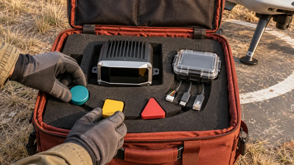
A 3D LiDAR development kit search usually hides a sharper engineering question: what evidence must a compact depth module, host computer, target set, and data handoff produce before an integration team spends time on perception logic? Treat “kit” as an evaluation package you define—not as a label that proves a sensor includes a driver, carrier, bracket, calibrated transform, or complete application.
For a first evaluation, the valuable outcome is a repeatable capture with known target, distance, lighting, host path, timestamp convention, coordinate frame, and data layout. That record lets a buyer compare candidates honestly and lets the software team start from evidence rather than a screenshot.
Quick answer
Define a 3D LiDAR development kit as four linked items: documented module facts, a controlled capture setup, a host-side data contract, and an acceptance record. The MRP-LD1 can be screened with its published depth/point-cloud output and UART, UVC, or UDP interfaces; its listing does not establish a native ROS driver, a supplied evaluation board, an end-to-end latency, or a complete safety function. Ask for the current documents and validate the installed path.
1. Define a 3D LiDAR Development Kit as an Evidence Package
There is a difference between purchasing a module and having a usable evaluation environment. A module may be appropriate for a project while still leaving the buyer to define power quality, mounting, a host adapter, data decoding, transforms, test targets, and test criteria. Make those open items explicit before comparing alternatives.
| Evaluation layer | Question to answer | Evidence to retain | Do not assume |
|---|---|---|---|
| Module facts | What published output, interface, range, FOV, size, power, and software-support fields fit the concept? | Supplier page version, dated spec extract, and the exact module identity. | That a listed interface proves a cable, driver, SDK API, or connector is included. |
| Physical capture | Can the installed sensor observe representative targets under declared conditions? | Mount drawing, target IDs, measured distance, target angle, lighting notes, and raw captures. | That a single depth image proves every surface, angle, or light condition will work. |
| Host path | Can the intended host receive, identify, store, and recover the chosen output? | Host OS/version, interface setting, packet or frame sample, restart record, and error log. | That Windows, ARM, Linux, or Android support means your particular board and application are ready. |
| Data contract | Can another engineer interpret each result in the same spatial and time context? | Timestamp meaning, frame name, units, layout, invalid-data rule, and transform record. | That a visually plausible cloud has enough information for downstream use. |
| Acceptance decision | Does the evidence meet this project’s documented objectives? | Pass/fail matrix, deviations, firmware/software versions, and open questions. | That published sensor parameters are project acceptance criteria by themselves. |
This approach complements the site’s compact dToF evaluation workflow: start with an observable result, then preserve enough context to repeat it. A short capture record is more useful to a buying team than an attractive, unlabelled point-cloud video.
2. Published MRP-LD1 Facts to Use as Screening Inputs
The Featured MRP-LD1 Drone LiDAR Sensor page is the product-fact source for this plan. The values below are screening inputs, not promises for an assembled kit or an installed application.
| Published field | MRP-LD1 listing | How to use it in a development plan |
|---|---|---|
| Sensing architecture | Solid-state SPAD dToF; 940 nm VCSEL | Record the sensor identity and verify the supplied unit/document revision before comparing captures. |
| Depth outputs | Real-time depth images and 3D point-cloud data | Decide which representation is the primary artifact and retain one unfiltered example of each needed output. |
| Resolution and frame rate | 40 × 30; 10 fps | Test target angular size, persistence, host processing, and data age in the actual evaluation setup. |
| Field of view | 60° horizontal × 45° vertical | Draw the installed viewing volume and validate it with real targets; do not treat nominal FOV edges as guaranteed usable rays. |
| Listed ranging baselines | 0.5–25 m indoors; 0.2–8 m outdoors | Choose project distances inside the relevant listed baseline, then document target and environment conditions. |
| Ambient-light reference | 80 klux | Include lighting, target finish, angle, protective window, and observed invalid data in the evidence record. |
| Interfaces | UART, UVC, UDP | Choose one first host path and state exactly what is decoded, stored, and recovered after interruption. |
| Software support | Windows, ARM, Linux, Android | Confirm the exact host, current document, data format, and implementation responsibility before integration. |
| Power and mass | 5 V; 1.2 W; 8 g | Budget the final cable, bracket, power path, connector, and protection separately from the module values. |
The current listing also gives accuracy bands by distance. Use the band applicable to a planned test distance as a question for the evidence plan, then measure the complete installed setup against the project’s own tolerance. Do not convert an accuracy field into a promise for a different target, mount, environment, or processing chain.
3. Build a Controlled Bench-to-Data Capture
A good first capture is deliberately modest. It proves that the selected host path and the physical setup can produce interpretable data. It does not attempt to prove every application behavior on day one.
- Freeze a baseline. Photograph the module mounting, identify the unit, record the host and power arrangement, and note the data path selected from UART, UVC, or UDP.
- Name the target set. Use representative project materials, sizes, surface finishes, and shapes. Give each target an ID instead of later describing it as “the dark one.”
- Measure the scene. Record sensor-to-target distance, target orientation, mounting height/pitch, and the light condition. If a window or cover will be installed, include it in a separate documented run.
- Capture raw evidence first. Save a limited number of unfiltered frames or packets along with the capture configuration. Only then make display or filtering changes for a downstream demo.
- Repeat one intentional change at a time. Change distance, target angle, light, or host configuration—not all four—so a reviewer can explain what moved the result.
- Exercise recovery. Restart the chosen stream or host path in a controlled setup and record how the receiving application identifies a renewed capture. Do not represent a one-time connection as integration proof.
Why make lighting and target choices explicit? A current SPAD-based dToF analysis identifies factors including optical photon flux, pulse width, time-of-flight quantization, and detector dead-time effects as part of ranging-performance analysis. That research does not transfer a numeric performance result to MRP-LD1; it supports a practical evaluation discipline: retain conditions rather than treating one favorable bench result as universal. See the 2025 dToF ranging-performance paper.
A minimal capture matrix
| Run ID | Controlled variation | Must be recorded | Review question |
|---|---|---|---|
| B0 | Baseline target and nominal distance | Module/host version, mount, chosen interface, raw output, units, and frame metadata. | Can the team open and interpret the baseline data? |
| T1–Tn | Target material, size, shape, or angle | Target ID, measured geometry, representative raw samples, and invalid-data behavior. | Which physical conditions require more evidence? |
| L1–Ln | Defined lighting or doorway/sunlight transition | Lighting description, protective-window state, target orientation, and data continuity. | Does the desired output remain reviewable under the declared condition? |
| H1 | Host restart or transport interruption | Interruption method, timestamps, recovery steps, observed restart behavior, and logs. | Can the host distinguish fresh from stale or missing data? |
4. Make the Host Handoff Traceable
If the evaluation will feed ROS 2, the official PointCloud2 definition is a useful checklist, not evidence that any module publishes ROS 2 natively. It describes a point cloud with a header, height and width, a field layout, byte order, point and row steps, data, and an invalid-point indicator. It also notes that time-of-flight sensors can produce organized 2D point clouds.
The linked ROS 2 Header definition separates a timestamp from the associated coordinate-frame identifier. Preserve that distinction whether your project uses ROS 2 or another middleware: “when was this observed?” and “in which frame is it expressed?” are different questions.
- State whether the timestamp means sensor acquisition, host receipt, decoded-frame completion, or application publication.
- Name the sensor optical frame and record the measured transform to the project reference frame; identify the convention, units, and sign directions.
- Describe depth units, point ordering, field types, endian handling when applicable, invalid values, confidence fields if present, and any conversion performed by the host.
- Record whether the output is organized, what each dimension means, and whether filtering or conversion changes the structure.
- Keep firmware, host OS, application/driver revision, document revision, configuration, and sample files together with the capture.
Choose transport on evidence, not familiarity. The UART, UVC, or UDP interface guide can help frame the selection. Then confirm current protocol and sample-data details through the available documentation resources. A listed interface and platform support do not, by themselves, settle framing, update behavior, API scope, or recovery responsibilities.
5. Illustrative Case: A Vertical-Fixture Depth Capture for a Packaging Cell
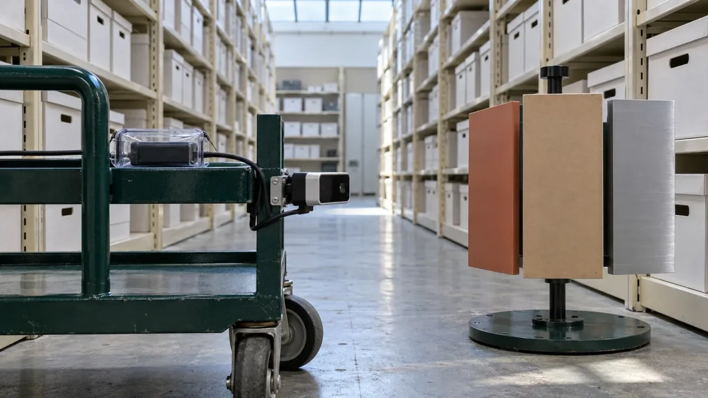
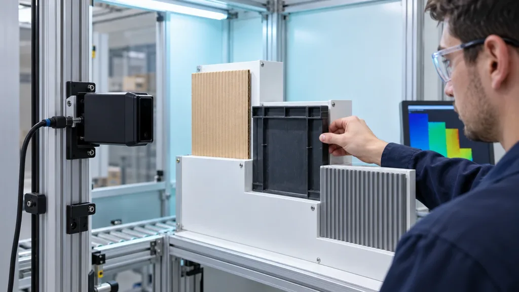
Illustrative engineering scenario—not a customer result: a packaging-equipment team is deciding whether a compact dToF module merits a second evaluation phase. It wants to distinguish a pale carton face, a dark reusable tote, and a ribbed separator at three declared distances in a fixed inspection cell.
The team mounts the sensor on a documented vertical rail rather than holding it by hand. It places the three materials on a stepped wall, labels them P1–P3, and captures the depth output through the selected host path. For every run, it records the module identity, optical-center position, target distance and angle, light condition, host version, and whether the frame contains invalid points.
One run changes only the target angle; a second changes only the light condition. The team saves the raw baseline before applying visualization palettes or point filtering. When a result is ambiguous, it creates a follow-up question—such as whether a production window, a different target finish, or a timestamp definition changes the conclusion—instead of declaring the module unsuitable from one image.
At handoff, another engineer can load the samples, understand their frame and timing metadata, repeat the placement, and see what software transformed the original output. That is a useful development-kit outcome: a bounded, reviewable integration baseline rather than a premature application claim.
Once you have representative samples, compare them with the site’s point-cloud dataset evaluation guide. If the decision is really about which output representation fits the downstream work, use the depth map versus point cloud guide before locking in conversion work.
6. Common 3D LiDAR Development-Kit Mistakes
- Calling a module a complete kit without checking. List what is physically supplied and what the buyer must provide.
- Showing a colored cloud without raw context. Retain the unfiltered source and declare the palette, filters, and units used for a view.
- Mixing time meanings. A sensor timestamp, a host-arrival time, and an application publication time can describe different events.
- Leaving the coordinate frame implicit. A correct cloud in an unknown frame is hard to compare, fuse, or reproduce.
- Changing multiple conditions at once. Separate target, angle, light, mounting, and host changes to preserve causality.
- Testing only a bright, front-facing target. Use a documented material and geometry set that resembles the project.
- Confusing published range with project acceptance. Range does not prove output continuity, target visibility, host data age, or application behavior.
- Assuming listed platform support proves a native middleware package. Confirm the current API, data format, host architecture, and conversion ownership.
- Promising a safety function from a bench test. Keep a module evaluation distinct from the project’s system safety, risk, and validation work.
7. RFQ and Evaluation-Sample Checklist
Send a testable request rather than “Please quote a 3D LiDAR development kit.” The following questions give both sides a practical starting point:
- Which exact module, hardware revision, firmware, document revision, and sample-data format are proposed?
- Which supplied items and which buyer-provided items make up the evaluation setup: power, cable, adapter, host, mount, target fixture, and protective window?
- Which of the listed UART, UVC, or UDP interfaces will be used first, and what current protocol/sample data is available for that path?
- What are the required target materials, dimensions, angles, distances, indoor/outdoor conditions, ambient light, and application geometry?
- What timestamp does the delivered data carry, what coordinate convention is used, and how are invalid or low-confidence observations represented?
- Which depth units, point fields, ordering, calibration information, and transform data are needed by the receiving host?
- What host OS, architecture, storage path, processing budget, restart behavior, and data-retention requirement apply to the evaluation?
- What pass/fail criteria, known limitations, acceptance samples, change-control expectation, and unresolved questions will close the first phase?
Turn Your Evaluation Question Into a Reproducible Capture
Share your target geometry, working distance, lighting, host platform, preferred interface, expected depth or point-cloud handoff, and the evidence you need before the next integration phase. Purpleriver can help compare those requirements with the MRP-LD1’s published parameters and prepare the right questions for an evaluation sample.