UAV integration guide
Drone LiDAR Sensor: A Body-Frame Alignment Check Before Flight
A drone LiDAR sensor can give sensible bench readings and still create a serious integration question once it is mounted: does the direction the sensor sees mean the same thing as the direction the aircraft and flight stack believe it means? This guide gives UAV teams an evidence-based way to prove that relationship before they use sensor data in a bounded flight evaluation.
Quick answer
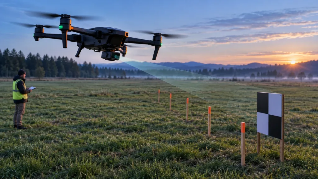
Document four things together before flight: the physical sensor face and mount angle; the body-frame direction assigned to its data; the usable view after airframe occlusions; and how the host handles valid, missing, stale, and out-of-range data. A target check on a fixed airframe, followed by a restrained-system check and a slow bounded outdoor check, is more useful than assuming a range value alone proves an avoidance-ready installation.
What body-frame alignment means for a drone LiDAR sensor
Forward is not a property of the sensor alone. It is the relationship among the sensing face, installed airframe, data representation, and control system. Record it in installation photos, a mounting sketch, and a test log. A level forward-looking module may be rotated in software; a deliberately tilted module may need a custom transform.
The official MAVLink Common Message Set makes the integration question concrete. Its DISTANCE_SENSOR definition includes orientation, horizontal and vertical field of view, range limits, and a custom body-frame quaternion. Its OBSTACLE_DISTANCE definition carries angular sectors, an angle offset, and a frame choice. These are protocol facts, not MRP-LD1 claims: if a host translates the module’s data into MAVLink, it must preserve the relevant meaning.
- Sensor face: identify the optical face and look direction with a physical arrow in photos.
- Vehicle reference: state which body axes the host uses and how the sensor face relates to them.
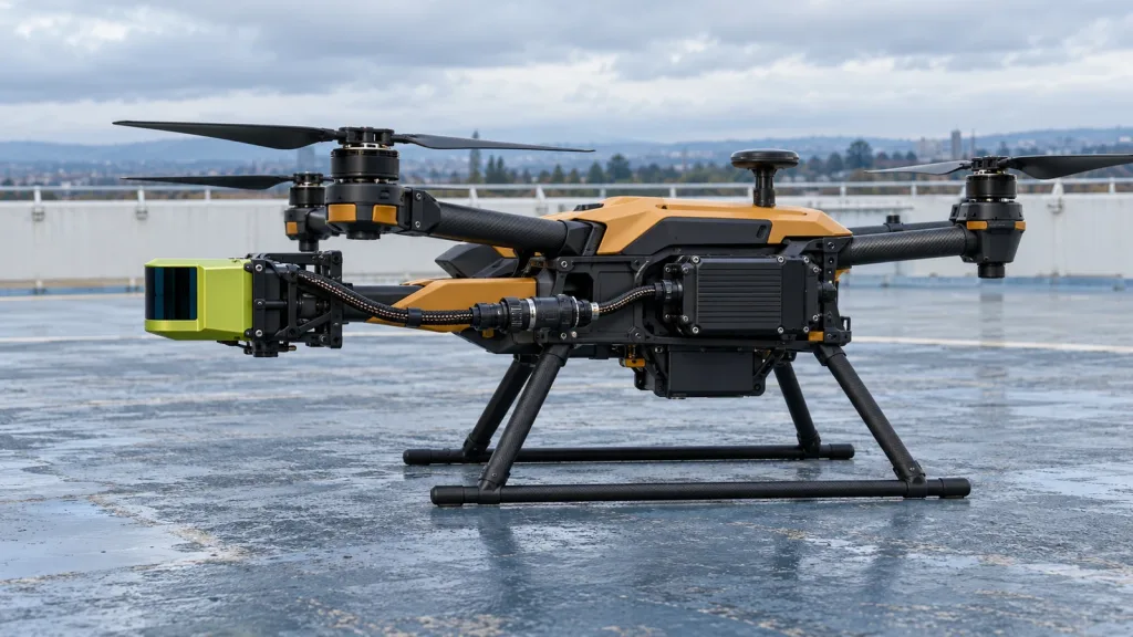
- Visible envelope: note propeller, landing-gear, fuselage, cable, and payload intrusion.
- Data boundary: distinguish a valid value, no target, invalid sample, and stale data.
Choose the evidence path before you fly
| Question | Minimum evidence | Do not conclude yet |
|---|---|---|
| Is reported direction correct? | Fixed airframe, known target in declared direction, mounting photo and frame map. | That one reading proves all-direction coverage. |
| Does installed FOV clear the airframe? | Target sweep with final payload, cable routing, and landing gear in place. | That the catalog FOV is unobstructed after installation. |
| Can the host interpret data safely? | Capture timestamp, units, range limits, orientation, validity state, and host conversion. | That output is natively understood by a flight controller. |
| Is a protection feature ready for a bounded test? | Confirm coverage, separation, delay, and mode behavior in that flight stack’s documentation. | That the sensor alone is a collision-avoidance system. |
Keep product facts separate from integration assumptions
Use the MRP-LD1 Drone LiDAR Sensor product page for product facts. The table uses the Featured-product export; it does not certify a particular aircraft installation, transform, flight mode, or avoidance result.
| Published MRP-LD1 item | Documented value | Use in this check |
|---|---|---|
| Architecture | Solid-state SPAD dToF LiDAR | Record module identity and supplied document revision. |
| Field of view | 60° horizontal × 45° vertical | Start here, then inspect installed occlusion. |
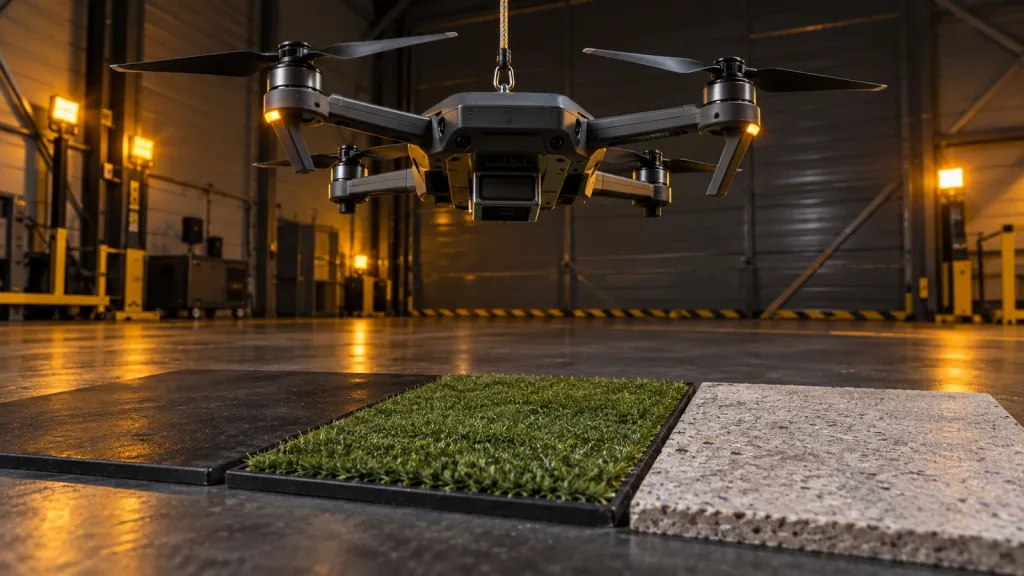
| Range baseline | 0.5–25 m indoors; 0.2–8 m outdoors | Use controlled targets within the documented baseline; validate target, light, angle, and motion. |
| Output | Depth images and 3D point-cloud data | Specify which output the host consumes and how it retains direction and validity. |
| Interfaces | UART, UVC, UDP | Choose one path and capture exact host settings and a data record. |
| Weight and power | 8 g; 1.2 W | Include the module in the airframe team’s payload, power, thermal, and vibration review. |
Build the sensor-to-host handoff before flight behavior
Choose the output that makes the first question testable. A depth image can reveal local occlusions; a point cloud can preserve spatial coordinates. Neither removes the need to state frames, units, timestamps, and invalid-data treatment. Use the site’s UART, UVC or UDP interface guide and depth map versus point cloud guide to prepare the handoff.
Make an acceptance capture with source timestamp, source interface, range units, physical target direction, reported sensor direction, vehicle-frame direction after conversion, validity/confidence state when available, and the host’s action. Do not infer native MAVLink support from the presence of UART, UVC, or UDP.
How should a drone LiDAR sensor report an installed direction?
Use a convention the receiver understands, then test it against targets placed in known directions. MAVLink’s distinction between a single range reading and angular obstacle sectors is why an installation photo and target sweep belong beside the data log.
A realistic application case: a bounded inspection-airframe evaluation
Scenario: A team prepares a compact multirotor for a slow, supervised infrastructure-inspection trial. Its sensor sits below the front payload area, and host-processed obstacle information is intended as pilot assistance. This is an evaluation scenario, not a claim of deployed performance.
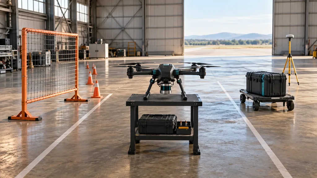
- With propulsion disabled, place a flat target in the stated forward direction and at useful-envelope edges. Save mounting photos plus raw and host-interpreted observations.
- Repeat with the intended payload, landing gear, and cables installed. Mark obscured or inconsistent sectors.
- In a restrained or prop-safe configuration, verify the actual power and interface path.
- Apply the selected flight stack’s own configuration guidance. PX4 states that Collision Prevention can slow or stop a multicopter from obstacle information, restricts motion where coverage is absent by default, and measures its configured minimum approach distance to the sensor rather than the outermost aircraft structure. Its official Collision Prevention documentation also calls out delay tuning and direction-dependent coverage.
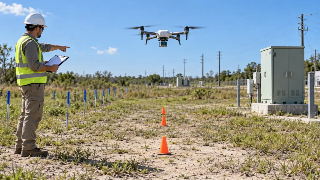
- Only then make a low-speed, supervised, bounded outdoor check with a documented stop condition and a log review before expanding the envelope.
Use the site’s distance and brake-margin guide for the wider stopping-distance discussion and its UAV navigation and obstacle-avoidance solution page for application context. Aircraft-level safety assessment and flight authorization remain the operator’s responsibility.
Common mistakes that make a clean bench result misleading
- Using catalog FOV as installed FOV: sweep targets after final geometry is present.
- Calling every packet forward: a value needs an explicit orientation convention.
- Collapsing no target, invalid, and out-of-range: retain distinct states for a deliberate host policy.
- Skipping timing: a correct direction without a measured end-to-end path is not a complete record.
- Equating sensing with avoidance: sensing is one part of a larger validated vehicle system.
- Testing an empty airframe: include the payload and cables used in the intended trial.
RFQ and evaluation checklist
Before requesting a sample, documentation, or project-specific quote, prepare an evidence brief:
- airframe type, payload layout, and intended sensor location;
- required look directions and accepted unknown sectors;
- target types, working distances, lighting, and motion;
- host operating system and preferred data output/interface;
- mounting angle, obstructions, and aircraft-team power/thermal/vibration constraints;
- bench, restrained, and bounded-flight evidence with stop condition and log format.
Request relevant manuals and evaluation material through the documentation resources page.
Turn the mounting question into an evaluation brief
Share your airframe layout, viewing directions, target distances, host interface, and trial environment. Purpleriver can start with documented MRP-LD1 information and relevant evaluation materials; your team should validate the final integration on its own vehicle.