UAV depth-data evaluation
40x30 Resolution LiDAR: A Ground-Grid Test for Drone Altitude-Hold Data
A 40x30 resolution LiDAR frame contains 1,200 depth samples, but that number alone does not show whether a downward-looking UAV installation will provide useful ground data at the heights, terrain textures, tilt angles, and controller handoff conditions in your prototype. The practical question is not “is 40x30 enough?” in isolation. It is whether the ground patch represented by those samples fits the altitude-hold task you intend to test.
This guide gives UAV integrators a repeatable ground-grid method. It uses the listed geometry of the MRP-LD1 Drone LiDAR Sensor product page as a worked example, while keeping a clear boundary between a published module specification and an aircraft-level result.
Quick answer
Use 40x30 output as a planning input, not a pass/fail claim. First calculate the approximate ground span from field of view and height. Then place real terrain pads inside that span, log the depth coverage and invalid samples, record mounting orientation and timing at the controller boundary, and only then run a controlled flight evaluation. A 1,200-sample frame can be useful when the required ground feature is well represented in the intended operating geometry; it does not by itself establish accuracy, detection probability, MAVLink compatibility, or safe altitude hold.
What 40x30 resolution LiDAR actually tells you
For a depth image, 40x30 means 40 columns by 30 rows: 1,200 reported depth positions in one frame. It says something about how finely the sensor partitions its field of view. It does not, on its own, tell you the size of the laser spot, the accuracy at every target, the behavior on a particular surface, the effect of propeller vibration, or how a controller will use the data.
The missing variable is geometry. At a greater height, the same angular field covers more ground, so the nominal spacing between neighboring samples grows. At a tilted mount, the footprint becomes asymmetric and moves away from the point under the aircraft. At a ground transition, vegetation edge, reflective puddle, gravel, or painted line, a nominal grid cell is not a promise that the feature will be reported cleanly.
That distinction matters for altitude-hold work. ArduPilot’s Surface Tracking documentation describes a downward-facing rangefinder in a low-altitude surface-tracking context and explains that behavior changes when the vehicle is outside rangefinder range. Treat that as a reason to validate the installed system in its intended envelope—not as proof that any particular LiDAR module has an ArduPilot driver or a safety approval.
Turn field of view into a ground-grid worksheet
For a first-pass worksheet, assume the optical axis is normal to a level test surface. At height h, the approximate ground span is:
span = 2 × h × tan(FOV ÷ 2)
Divide horizontal span by horizontal samples and vertical span by vertical samples to get a nominal center-to-center grid pitch. This is a geometric planning estimate, not a claim about instantaneous field of view, optical spot size, ranging accuracy, or a minimum detectable object.
| Example height | Approx. horizontal span | Nominal horizontal grid pitch | Approx. vertical span | Nominal vertical grid pitch | What to observe |
|---|---|---|---|---|---|
| 1 m | 1.15 m | 29 mm | 0.83 m | 28 mm | Whether small terrain transitions occupy several neighboring depth positions. |
| 2 m | 2.31 m | 58 mm | 1.66 m | 55 mm | Whether the intended ground patch is still covered without excessive invalid regions. |
| 4 m | 4.62 m | 115 mm | 3.31 m | 110 mm | Whether the planned feature size still makes sense for the task; do not infer that it will be detected. |
Use your approved test heights rather than copying these examples. If the mount is pitched, record the actual orientation, re-measure the footprint, and place the test pads where the installed field—not an ideal top-down diagram—looks.
| Decision question | Use the worksheet for | Physical evidence to collect | Do not conclude |
|---|---|---|---|
| Does the target ground area fit the frame? | Estimate the ground span at each test height. | Photo of the marked footprint and a raw depth frame. | That every ground feature will be detected. |
| Is the terrain transition represented? | Choose pad widths and heights that create a meaningful test. | Coverage percentage, invalid samples, and repeated captures. | That nominal grid pitch equals ranging accuracy. |
| Is the aircraft orientation accounted for? | Identify the expected downward axis and offset. | Mount photo, orientation record, and level-reference check. | That the sensor’s interface automatically configures the flight controller. |
| Can the data reach the controller? | Define the fields that must be visible in a handoff log. | Timestamped sample record and integration test evidence. | That a listed UART, UVC, or UDP interface is MAVLink by default. |
Exact MRP-LD1 parameters to put on the test sheet
The following facts are from the Featured-product export for the MRP-LD1 Drone LiDAR Sensor. They are useful for selecting a test range and data path; they are not aircraft-level performance guarantees.
| Ranging principle | SPAD dToF |
|---|---|
| Light source | 940 nm VCSEL |
| Output resolution and frame rate | 40×30 and 10 fps |
| Field of view | 60° horizontal × 45° vertical |
| Listed ranging capability | 0.5–25 m indoors; 0.2–8 m outdoors |
| Interfaces | UART, UVC, UDP |
| Power and weight | 5 V, 1.2 W, 8 g |
| Listed scope | Includes UAV obstacle avoidance, altitude hold, and terrain following |
Before choosing a transport, review the site’s UART, UVC, or UDP interface guide. The listing confirms those interfaces; it does not state that the module publishes MAVLink, contains a particular flight-controller driver, or has a particular end-to-end latency. Those are items to confirm and test.
Run a six-step ground-grid test before a controlled hover
- Write the task boundary. State the planned height band, terrain type, required ground patch, aircraft orientation, controller, and what an acceptable raw observation looks like. Do not label the result “safe” at this stage.
- Mark the calculated footprint. At each intended height, mark the approximate horizontal and vertical span on a level test surface. Add a note for actual mount pitch and sensor offset.
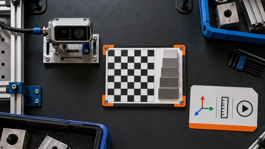
- Place mixed-height terrain pads. Use physical pads with known dimensions, plus at least one low-contrast or texture-changing surface that represents the intended environment. Keep their location inside, near the edge of, and outside the calculated footprint.
- Capture raw output repeatedly. At a stationary bench or restrained-aircraft stage, save frames or packets for each height, angle, and surface. Record invalid values, empty regions, and any change after repeated captures. A useful frame is evidence; it is not a generalized claim.
- Check the handoff record. Confirm that your integration path preserves the necessary timestamp, orientation, range-bound, and validity information. Use the MAVLink DISTANCE_SENSOR definition as a transparent example of the kinds of range, orientation, covariance, and FOV fields an integration record may need. It is not evidence that the sensor itself speaks MAVLink.
- Move to a controlled flight evaluation. Only after the data and orientation records pass your written criteria should the team carry out an appropriately controlled, site-approved flight test. Compare the live behavior with the ground-grid observations and retain the conditions with the result.
For broader context on test sequencing, see the site’s dToF LiDAR evaluation workflow. It helps keep a component evaluation separate from a claim about a complete aircraft.
Make the interface and controller handoff inspectable
“Depth data arrived” is not a sufficient log entry. A useful handoff record lets another engineer reconstruct what the controller was asked to consume. At minimum, record the source interface, message or packet version, timestamp basis, sensor orientation relative to the airframe, minimum and maximum bounds, any confidence or invalid-value convention, and the height and surface used in the test.
The official MAVLink definition names fields such as current distance, min/max distance, orientation, covariance, and horizontal/vertical FOV. Your implementation may use a different protocol; the point is to make equivalent meaning inspectable instead of silently reducing a 3D depth frame to an unexplained scalar. If the system converts the frame to a controller input, save one raw input and one converted record from the same test event.
Where a project needs a depth image and a point cloud for different checks, the depth map versus point cloud guide provides useful terminology. Calibration work should also identify the physical sensor-to-airframe relationship; OpenCV’s calibration documentation is a helpful reference for keeping geometry and calibration explicit.
Application case: evaluate a low-altitude survey hover over mixed ground
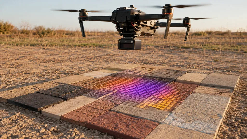
Imagine a UAV team that wants to evaluate altitude-hold data while surveying an access track that transitions between compact soil, a shallow raised repair strip, and coarse gravel. The team chooses its own approved low-altitude test heights, then marks the corresponding nominal footprints from the worksheet. It places pads representing the repair strip inside the middle of the footprint, near the field edge, and just beyond it.
At each height, the team collects stationary raw data first, then repeats the capture after a small mount-angle adjustment. The evaluation sheet records how many cells cover each pad, whether invalid values cluster on a material transition, the orientation used for the data path, and the exact data seen by the controller-side bridge. Only then does the team schedule a controlled hover evaluation under its own flight procedures.
The result is a decision record: “this geometry and handoff produced this observed coverage under these conditions.” It is deliberately not “40x30 works for all altitude-hold missions.” For a related low-altitude process, read the site’s low-altitude control validation guide.
Common mistakes that make a resolution test misleading
- Equating cell count with accuracy. A nominal 29 mm grid pitch at 1 m is a geometric calculation, not a ±29 mm measurement claim.
- Testing only the center of the field. Put terrain pads near the expected footprint edge and outside it, then log the result.
- Ignoring mount angle. A small pitch change can move the footprint and make a level-surface worksheet invalid.
- Calling an interface a controller protocol. UART, UVC, and UDP describe listed interfaces; document the actual payload and bridge behavior before claiming compatibility.
- Using a polished depth screenshot as the only artifact. Retain raw captures, conditions, invalid values, and controller-side evidence.
- Skipping environmental variation. A smooth indoor floor does not represent every outdoor surface, lighting condition, vibration level, or vehicle attitude.
RFQ and evaluation checklist for a 40x30 altitude-hold prototype
| Ask or record | Why it belongs in the decision file |
|---|---|
| Exact requested output, frame rate, FOV, interface, and range band | Prevents the test plan from drifting away from the listed module facts. |
| Aircraft mount drawing with optical-axis orientation and offset | Lets the team recompute the actual ground footprint. |
| Test heights, terrain-pad dimensions, materials, and locations | Makes coverage observations repeatable rather than anecdotal. |
| Raw frame/packet plus converted controller-side record | Shows whether data meaning survived the handoff. |
| Invalid-value, confidence, range-bound, and timing treatment | Exposes data-quality assumptions before a flight test. |
| Written acceptance criteria and retest conditions | Separates an observed result from a broad performance promise. |
Turn the worksheet into an evaluation conversation
If you are comparing a compact dToF module for a UAV depth-data prototype, bring your expected height band, ground feature size, mount sketch, controller boundary, and required records to the first technical discussion. Contact Purpleriver to discuss the documented MRP-LD1 parameters and the evidence you need for your evaluation; confirm any integration details that are not listed on the product page.
FAQ
Is 40x30 resolution LiDAR enough for drone altitude hold?
It can be a useful starting point only if the intended ground patch is adequately represented at the installed height and angle, and the data/handoff behavior is observed in a controlled evaluation. Resolution alone cannot answer the question.
How many samples are in a 40x30 depth frame?
There are 1,200 positions: 40 columns multiplied by 30 rows.
Does nominal grid pitch equal ranging accuracy?
No. Grid pitch is a geometric spacing estimate derived from field of view, height, and sample count. Accuracy is a separate specification and must not be inferred from it.
Why does mounting height matter so much?
The same angular field covers a larger ground area as height increases, so nominal spacing grows and the location of the footprint changes with the installed geometry.
Should I test with the sensor aimed straight down?
Test the orientation your aircraft actually requires. A normal-to-ground calculation is useful only as a starting worksheet; record any pitch, roll, offset, and actual field placement.
Does the MRP-LD1 product listing confirm MAVLink or ArduPilot support?
No. The listed interfaces are UART, UVC, and UDP. Confirm the actual payload, bridge, flight-controller compatibility, and behavior with the supplier and your own integration test.
What should I log when evaluating controller handoff?
At minimum, log the interface and message version, timestamp basis, orientation, range bounds, validity/confidence treatment, test height, surface, raw input, and converted controller-side record.
Can a successful indoor ground-grid test prove outdoor performance?
No. It is evidence for the recorded conditions only. Repeat the test across the actual surfaces, lighting, vehicle attitudes, and operating conditions relevant to your program.