UAV integration worksheet
UAV Obstacle Avoidance dToF Module: Build a Coverage-Ownership Worksheet
A UAV obstacle avoidance dToF module can provide useful forward depth information, but a useful module specification is not the same thing as an all-direction collision-avoidance claim. Before the first supervised flight, make one team-owned record that states what sector is observed, which readings are usable, how they reach the flight stack, and what remains unknown.
Quick answer
Start with the sensor’s listed field of view, place a deliberately limited test sector in front of the airframe, and record the target, distance, mounting orientation, data timestamp, valid/invalid reading behavior, and the controller-side interpretation. Treat every unobserved sector and every unverified data conversion as an explicit boundary—not as empty space that the aircraft can safely ignore.
What “coverage ownership” means for a UAV obstacle avoidance dToF module
Coverage ownership is a plain-language agreement between the airframe, sensor, companion-computer, and flight-control teams. It answers four questions: which physical sector is intentionally observed; what input counts as a valid obstacle indication; who verifies the translation into the controller’s frame; and what action remains with the remote pilot when the measurement is unavailable, ambiguous, or outside the declared sector.
This is important because a forward-looking sensor may be appropriate for a forward task without representing the rear, sides, top, or any part of the scene blocked by airframe structure. ArduPilot’s current rangefinder guidance likewise separates forward-facing rangefinders from omnidirectional proximity systems and cautions that the configured maximum must be a tested, appropriate value. Review the current rangefinder guidance before mapping a device into an avoidance configuration.
The worksheet is also a useful procurement artifact. It tells a supplier exactly which evidence a pilot build needs, while keeping the decision grounded in the actual airframe and flight-stack behavior rather than a single range figure.
Coverage-ownership decision chart
| Question | If the answer is documented | If the answer is not documented |
|---|---|---|
| Which physical sector is in view? | Sketch the sensor boresight, the stated field of view, and airframe occlusions on the worksheet. | Keep the use case in supervised data capture; do not describe the sector as covered. |
| Which target and range conditions were tested? | Log target type, distance, angle, ambient condition, and observed valid/invalid output. | Schedule a bounded ground or tethered test before any avoidance tuning. |
| Does the host receive a traceable distance representation? | Record interface, message mapping, timestamp, units, frame, and invalid-value handling. | Stop at interface bring-up; a visible stream is not yet a controller-ready input. |
| What happens outside the declared sector? | Assign a pilot procedure, mission constraint, or another sensing method. | Mark the area as an open risk, not as a coverage assumption. |
MRP-LD1 facts to place on the worksheet
The MRP-LD1 Drone LiDAR Sensor product page is the factual starting point for an evaluation sheet. The values below are listed product facts, not a claim that a particular UAV or controller configuration will achieve a particular avoidance outcome.
| Listed product field | MRP-LD1 value | Worksheet use |
|---|---|---|
| Technology | SPAD dToF solid-state LiDAR with 940 nm VCSEL | Identify the sensing approach and retain the source revision. |
| Ranging capability | 0.5–25 m indoors; 0.2–8 m outdoors | Use as a starting envelope, then record the exact test conditions. |
| Field of view | 60° (H) × 45° (V) | Draw the declared forward sector and check for airframe occlusion. |
| Output and rate | 40 × 30; 10 fps | Identify whether the downstream workflow uses depth, point cloud, or a derived sector representation. |
| Interfaces | UART, UVC, UDP | Write the chosen physical/data path and its owner. |
| Integration facts | 5 V; 1.2 W; 8 g; Windows/ARM/Linux/Android software support | Check power, mass, host, and documentation fit on the actual airframe. |
A 40 × 30 output contains 1,200 cells, but the worksheet should not quietly turn those cells into a promise of 1,200 independently verified obstacles. First define how the host groups, filters, or rejects readings for the particular flight-stack handoff. The existing depth-map versus point-cloud guide can help the team choose the data representation before integration work begins.
Realistic case: a supervised forward-sector acceptance test
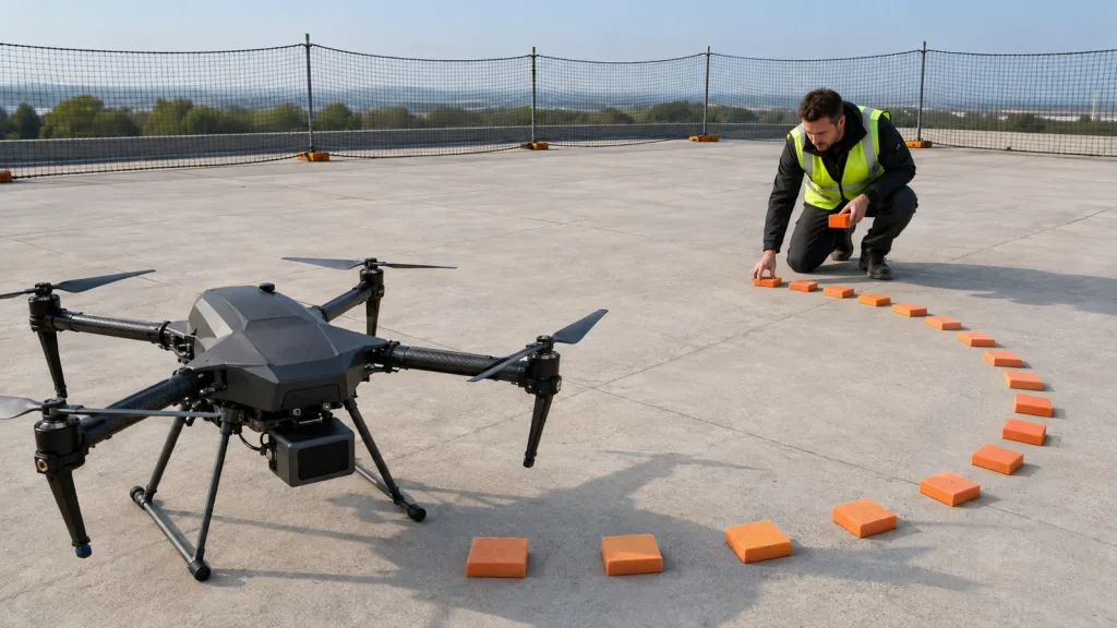
Consider a compact multirotor fitted with the module below its nose for a low-speed, forward-only inspection approach. The team marks a narrow, open test pad with soft, high-contrast foam markers that stay inside the declared forward sector. The aircraft remains restrained or in a controlled ground test while the team moves one marker across the sector at several planned positions.
For each position, record the physical marker location, target face angle, lighting note, sensor output, host timestamp, selected interface, and the value the flight stack receives. Repeat with a marker just outside the drawn boundary. That outside result belongs in the record even when it is empty or inconsistent: it demonstrates where the team has stopped making an observation claim.
Use the existing dToF LiDAR drone evaluation workflow for broader evaluation preparation, but keep this worksheet focused on accountable sector boundaries and data handoff.
From depth output to a controller-ready data handoff
Choose one interface for the first test and preserve a raw capture. The product lists UART, UVC, and UDP; each can be suitable for a different host design, but the correct choice is the one whose data path your team can inspect end to end. For practical comparison criteria, see UART, UVC, or UDP: choosing the right LiDAR interface.
If a companion computer converts depth data into an obstacle representation, define the translation explicitly. The current MAVLink OBSTACLE_DISTANCE message definition includes indexed distances, angular increment, minimum and maximum measurable distance, angle offset, and a coordinate frame. Those fields are a useful handoff checklist even when your final path uses another protocol: the receiving team should be able to identify units, angular meaning, vehicle-relative orientation, unknown data, and the age of each value.
Keep the sensor stream and the controller interpretation as two separately signed-off items. A serial or video device that enumerates successfully does not, by itself, prove that the aircraft is receiving correctly framed, current, and usable proximity information. The site’s LiDAR sensor data-contract guide offers a complementary way to document those fields.
Condition logging is not bureaucracy. A 2025 peer-reviewed analysis of SPAD-based dToF ranging shows that precision limits can depend on effects including detector dead time, photon flux, pulse width, and time-of-flight quantization. Use the paper's accessible primary record as a technical reference, then record your own target and scene conditions rather than carrying a laboratory conclusion into a flight claim.
Common mistakes that weaken a coverage plan
- Calling a forward field of view omnidirectional coverage. Label the observed sector and document every unobserved direction.
- Using a listed maximum as a tuning constant. Use a tested value appropriate to the actual setup, target, and controller configuration.
- Testing only a centered, favorable target. Include boundary positions and record invalid or unexpected readings.
- Skipping frame and unit ownership. A distance value without an orientation, timestamp, units, and invalid-value convention is not ready for a safety-relevant handoff.
- Letting “connected” replace “verified.” Keep raw logs and a controller-side record for the same test event.
- Turning the worksheet into a flight authorization. It is an engineering artifact; operating procedures and pilot responsibility still apply.
If a stream looks plausible but the handoff is not reproducible, work through the site’s common LiDAR integration diagnostics before adding more autonomy.
RFQ and evaluation checklist
- Name the airframe, mounting location, intended forward sector, and all expected occlusions.
- Request the current interface/protocol material for the selected UART, UVC, or UDP path.
- Confirm the listed 5 V, 1.2 W, and 8 g integration values against the platform budget.
- Define the target set, boundary positions, test distances, and environmental notes before collecting data.
- Specify valid, invalid, no-return, and stale-data behavior for the host application.
- Record units, axes, angle offset, field-of-view boundary, timestamp source, and message mapping.
- Assign an owner for sensor mounting, host conversion, flight-stack configuration, and pilot procedure.
- Set a review gate: no autonomous response claim until the raw capture and received-controller record agree for the chosen test set.
Turn a module inquiry into an integration-ready evaluation
Send Purpleriver your airframe layout, proposed coverage sector, host interface, and test conditions. The team can start with the MRP-LD1’s listed facts and help you prepare a focused evaluation conversation without replacing your flight-test or operating procedures.
Discuss an MRP-LD1 evaluation or review the module evaluation-sample checklist first.