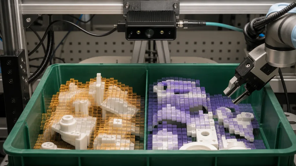
3D depth sensor projects for a parts-picking prototype rarely fail because the team cannot produce a striking depth image. They fail because the first bench demo does not show what is hidden in a real bin, the capture cannot be related to the robot frame, or the perception team receives data with no repeatable record of how it was produced.
This guide is for robotics integration leads and technical buyers who need to decide whether a compact depth module deserves a controlled bin-feasibility pilot. It is not a claim that any specific sensor is a finished bin-picking solution. It is a way to make the pilot honest: define the part bin, coverage, calibration evidence, output handoff, and reject conditions before approving more hardware or software work.
| Quick answer | Choose the output your host can inspect, then test a repeatable cluttered bin—not a single staged object—with its calibration and capture settings recorded. |
|---|---|
| Best first pilot | A fixed mounting position above a defined bin, a small set of real parts at several heights, and a documented replay package for the perception team. |
| Approval rule | Do not approve a sample solely because a colorful depth view looks plausible. Approve only when the intended downstream team can reproduce the capture, interpret the frame and validity rules, and state what constitutes a missed part or unusable pose. |
What a bin-picking pilot must prove
A bin-picking prototype needs useful geometry, not merely object visibility. NIST describes 3D imaging as a way to obtain the spatial information needed to calculate the position and orientation of objects for random bin picking; that is a useful reason to test real clutter rather than a single clean target. The practical question is whether the mounting geometry, part surfaces, occlusion, and output handoff give your own perception workflow enough evidence to continue.
Start by writing the pilot boundary in one sentence: “We need to determine whether this mounting position and this output can support a repeatable candidate pose for these parts in this bin.” That boundary prevents two costly errors: treating an attractive demonstration as a production promise, and asking a sensor supplier to guarantee the behavior of an untested gripper, robot, or software stack.
For a useful pre-read, review how to evaluate a LiDAR point-cloud dataset before integration. The missing step for a parts bin is connecting that data review to the real mounting position, bin wall, component height, and the evidence a software team needs to replay the capture.
3D depth sensor: choose the output before the sample
The word “depth” can hide a major handoff decision. A depth image preserves a grid of measured values by pixel; a point cloud represents geometry as points with fields and layout that a host must understand. ROS 2 maintains dedicated interfaces for both camera information and point-cloud data, which is a useful reminder that the capture data and the information needed to interpret it belong together. It does not mean that a particular module provides a ROS driver, a particular message type, or a ready-made bin-picking pipeline.
| What the pilot team needs | Output to ask about | Evidence to capture | Do not proceed if |
|---|---|---|---|
| Inspect where the sensor has depth across the bin | Organized depth image or grid, plus its dimensions and units | Raw capture, mounting position, capture settings, invalid-value rule, and calibration information | The team cannot tell a missing or invalid measurement from an actual near value |
| Pass 3D geometry to an existing perception stack | Point cloud with documented coordinate frame, fields, and timestamp behavior | A recorded cloud, field layout, coordinate-frame definition, and one replay instruction | The host cannot parse the layout or relate the cloud to the bin or robot frame |
| Screen feasibility before choosing the final stack | A deliberately limited capture package, not a vague “demo output” | Matched depth/point data where available, calibration/context files, and test photos of the bin layout | The result can only be viewed in a vendor-specific viewer and cannot be independently reviewed |
| Decide whether occlusion is acceptable | Repeated captures of the same varied-height arrangement | Part count, part positions, wall contact, capture distance, and an agreed missed-area rule | One arrangement is used to claim coverage for every arrangement |
If the downstream team works in ROS 2, the official sensor message documentation is a good vocabulary check: it distinguishes image, camera-information, and PointCloud2 concepts, and includes point-cloud parsing tools. Use that vocabulary to ask what your own host needs; do not assume a listed physical interface automatically supplies every software field.
Featured-product facts to evaluate first
For this workflow, the current WooCommerce Featured product is the MRP-LD1 Drone LiDAR Sensor. The facts below are the supplied product fields to evaluate against your own pilot geometry. They are not evidence of bin-picking compatibility, robot integration, or pose performance.
| Published product field | Exported value | How to use it in the pilot |
|---|---|---|
| Ranging / scanning principle | dToF / SPAD, 940 nm VCSEL | Record it as part of the tested configuration; do not infer performance on untested part materials. |
| Output and frame rate | 40×30 output; 10 fps | Ask whether the host can preserve and inspect the organized output at the pilot’s actual capture cadence. |
| Field of view | 60° horizontal × 45° vertical | Draw the usable bin envelope from the proposed mounting location before ordering brackets or writing gripper logic. |
| Listed range | 0.5–25 m indoors; 0.2–8 m outdoors | Keep the experiment within the listed context, then record actual sensor-to-bin geometry rather than treating the range listing as a pose claim. |
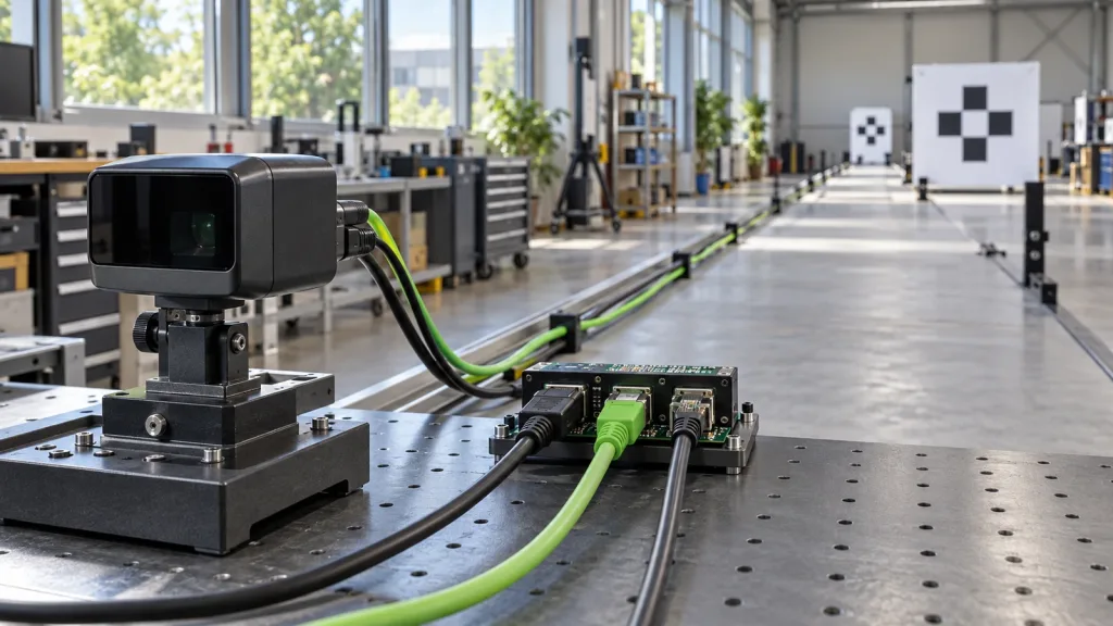
| Interfaces | UART, UVC, UDP | Choose the transport your evaluation host can log and replay; confirm packet or stream details from supplied documentation. |
| Integration constraints | 5 V, 1.2 W, 8 g; Windows, ARM, Linux, Android support | Check mounting, power, and host constraints early, without assuming connector, driver, or protocol details that are not supplied. |
Purpleriver lists robot navigation, obstacle avoidance, SLAM, UAV, AR/VR, industrial inspection, and security among the product’s stated application scope. A bin-feasibility exercise should therefore remain an evaluation question: request the documentation, mount the module safely, and accept or reject the pilot using your own evidence. For related early work, see visualizing dToF depth data for early product testing.
A four-stage coverage, calibration, and handoff workflow
1. Freeze the bin and part set
Photograph the empty bin, record its inside dimensions, and define a small but realistic set of parts: the tallest, shallowest, most reflective, darkest, and most nested arrangement you expect in the first prototype. Do not call a part “detected” until your team has defined the visible geometry or pose evidence it needs.
2. Test the physical coverage before writing perception rules
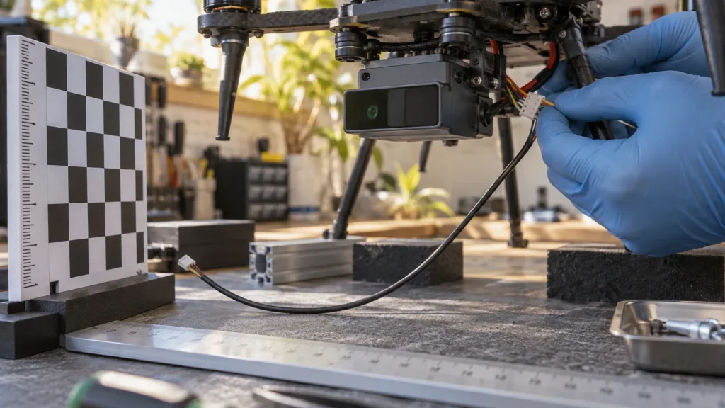
Mount the sensor at the exact height, pitch, and lateral offset the prototype can actually accommodate. Place parts at the center, corners, near walls, and at different stack heights. Repeat the same arrangements after small controlled changes. The goal is to find blind regions and occlusion patterns early—not to tune them away in a presentation.
3. Preserve calibration and context with every capture
For camera-like data, calibration is not an optional screenshot. The official ROS 2 CameraInfo specification documents how calibrated image dimensions and camera parameters describe an image stream. Even if your host does not use ROS, retain the equivalent supplier-provided calibration/context and record the resolution, mounting transform, coordinate-frame convention, timestamp basis, and any relevant configuration version. That is what lets another engineer decide whether a depth value can be related to a bin or robot frame.
4. Deliver a replayable package, then judge the pilot
Give the perception team the raw or documented output, calibration/context, capture notes, bin photographs, and the pass/fail rule. NIST’s work on uncertainty in 3D imaging is a useful discipline here: treat orientation and spatial results as things to evaluate with a stated method, rather than as a visual impression. If the team cannot replay a representative capture or explain an invalid region, the pilot has produced a question—not an approval.
Interface and data-delivery questions
The MRP-LD1 listing names UART, UVC, and UDP. Those are transport options, not a substitute for a data contract. Before a sample is approved, ask which transport is available to your evaluation host, how the host receives the output, what information documents its units and validity, and how a capture can be archived. Do not invent a connector, packet format, ROS topic, robot-controller support, or SDK behavior from the interface names alone.
- Which output will the host log: an organized depth grid, a point-cloud representation, or another documented stream?
- What coordinate frame and timestamp convention apply to each capture?
- How are out-of-range, missing, or invalid values represented?
- Which calibration or configuration material must accompany the captured data?
- Can a second engineer replay the package without relying on a live viewer?
Use the existing guide on choosing UART, UVC, or UDP for a LiDAR interface to compare transport fit, then use the questions above to define the information that must cross the chosen transport. If a capture behaves unexpectedly, the site’s guide to common LiDAR integration issues can help structure a diagnosis without rewriting the pilot history.
Illustrative case: a bounded kitting-bin feasibility test
Scenario, not a customer result: an automation team wants to explore whether a compact 3D depth sensor could provide useful geometry above a divided kitting bin of white molded housings. The team does not assume a final robot or gripper solution. It mounts the sensor on an adjustable rail, marks the bin frame, and creates eight repeatable part arrangements: empty bin, one part in each corner, nested pairs, a tall part near the wall, and a mixed-height arrangement.
For each arrangement, the team stores the capture, mounting position, part photograph, frame/calibration context, and an observation such as “corner hidden by wall” or “top face visible but lower cavity not represented.” The perception engineer then replays the same package and decides whether the available geometry is enough to produce a candidate pose. The pilot passes only if the team can explain its known blind areas and reproduce the outcome—not because every part is magically solved.
Common mistakes that make a 3D depth-sensor pilot inconclusive
- Testing one clean part on a table: it says little about bin walls, overlap, or stacked heights.
- Changing the mount between captures without recording it: this makes it impossible to separate geometry from configuration changes.
- Calling every blank value “far away”: missing, invalid, and out-of-range data need a documented interpretation.
- Using an attractive visualization as the only deliverable: the software team needs a replayable capture and context, not just a screenshot.
- Promising integration from an interface label: UART, UVC, and UDP do not by themselves establish packet semantics, driver support, or robot compatibility.
- Claiming bin-picking performance from a product fact table: exact product fields are inputs to an experiment, not a substitute for it.
RFQ and evaluation checklist
| Ask before approval | Evidence to request or create | Owner |
|---|---|---|
| What parts and bin geometry are in scope? | Part list, bin photos, dimensions, and eight or more repeatable arrangements | Automation / process team |
| Where can the sensor physically mount? | Height, pitch, lateral offset, interference notes, power route, and fixed frame definition | Mechanical / electrical team |
| Which output will the host accept? | Written depth-image or point-cloud requirement, units, field layout, timestamp and invalid-value expectations | Perception / software team |
| What proves calibration context is preserved? | Supplier documentation or configuration files, resolution, transform convention, and capture version record | Integration lead |
| What constitutes pilot success? | Known coverage boundary, replayable data package, stated false/unknown cases, and next-step decision | Cross-functional review |
Turn the first sample into a reviewable engineering decision
Before requesting an MRP-LD1 evaluation path, prepare the bin geometry, output questions, and replay checklist above. Then use Purpleriver’s documentation resources to request the material needed to match a proposed host and test setup.