UAV side-sector integration guide
Right Obstacle Sensing is complete only when a physical target on the aircraft’s right becomes a correctly angled, fresh, controller-visible measurement—and the intended flight mode responds as designed. A side-mounted sensor is the beginning of that chain, not proof that the chain works.
This distinction matters because detection, transport, fusion, and intervention are separate functions. A depth image can look correct on a laptop while the autopilot receives the wrong angle. A controller can display a right-side obstacle while a particular mode does not use that data for avoidance. A clean bench stream can also become stale after it passes through a driver, companion computer, serial link, middleware, and estimator.
The practical goal is therefore not “make the sensor see a wall.” It is “prove a traceable right-sector observation from target to vehicle behavior.” If your larger project is still defining range and braking requirements, use the separate guide to drone obstacle-avoidance distance and brake margin. This article stays focused on the side-sector chain.
1. Define Aircraft-Right Before Touching Hardware
Write down the coordinate convention used at every interface. “Right” is obvious to a person standing behind a level aircraft, but software may represent direction as a sensor-local angle, a vehicle-body angle, a quaternion, an orientation enum, or a pre-rotated sector index. If any two stages disagree, a right-side target can appear forward, left, or nowhere.
For example, the official MAVLink OBSTACLE_DISTANCE definition allows an angular offset for the first bin. In a body-fixed FRD frame, its documentation describes zero degrees as forward and positive angles as clockwise. That makes +90° nominally aircraft-right. This is a protocol convention, not permission to assume that every driver or flight stack has already rotated your sensor data into it.
Create an angle ledger before integration:
| Boundary | Frame or convention to record | Evidence to retain |
|---|---|---|
| Physical installation | Sensor optical axis relative to aircraft forward, right, and down | Dimensioned mount drawing, photos, measured yaw/pitch/roll |
| Depth output | Pixel origin, horizontal order, vertical order, and invalid-value rules | Interface document and annotated target sweep |
| Driver or companion computer | Sensor-to-body rotation and timestamp origin | Configuration, commit/version, and message capture |
| Flight-controller input | Message frame, angle offset, increment, orientation, minimum and maximum distance | Decoded message and controller parameters |
| Avoidance behavior | Mode, margin, stale-data behavior, and operator override | Test card, log, and pass/fail result |
A useful bench check is directional, not just metric. Place one target on the right and keep the other sectors clear. Then move the target forward-right, directly right, and rear-right. The controller-side sector indication should move in the same sequence. Repeat with the sensor temporarily reversed or with a known configuration change; a test that cannot fail is not a useful test.
2. Build a Right-Sector Evidence Chain
Treat the integration as six linked claims. Each claim needs its own observable output:
- Optical claim: the target produces a valid return in the raw depth frame.
- Geometric claim: the return is assigned to the correct ray or angular region.
- Transformation claim: the sensor-local direction becomes the intended aircraft-body direction.
- Semantic claim: near, clear, invalid, out-of-range, and stale states remain distinguishable.
- Transport claim: the controller receives data at a measured rate and age under realistic load.
- Behavior claim: the intended controller mode consumes the sector and produces the project-defined warning, limit, or maneuver.
Do not skip from claim one to claim six. If the vehicle fails to slow during a lateral test, the chain lets the team locate the failure without guessing. If the raw depth frame is correct but the right sector is empty in the flight log, the problem lies after perception and before controller ingestion. If the sector is visible but there is no motion response, inspect mode and avoidance configuration rather than changing the optics.
This boundary-by-boundary approach complements the broader LiDAR sensor data-contract guide. For right sensing, add a direction-specific acceptance rule at every boundary.
3. Check Mounting, Field of View, and Occlusion
A right-looking installation is defined by measured orientation, not by the side of the airframe where the enclosure sits. The optical axis can be offset by mount tolerances, a canted arm, landing-gear geometry, or an installation intended to see both right and slightly downward. Record the final installed yaw, pitch, and roll after fasteners are torqued.
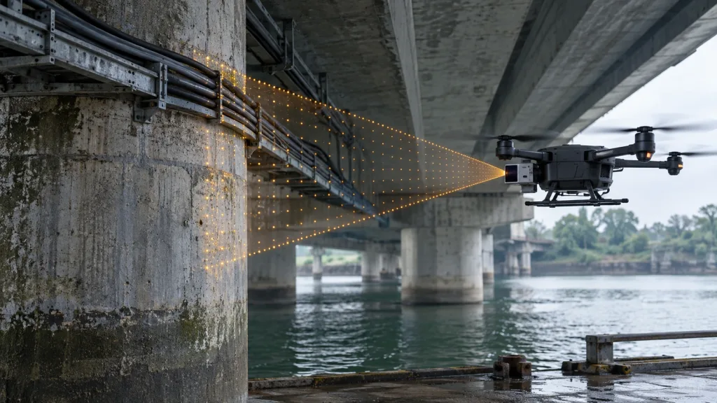
As a geometric example—not a factory preset—consider a calibrated optical axis mounted at +90° yaw in the body convention above. A 60° usable horizontal field of view would nominally span +60° to +120°. Masking, lens calibration, vehicle structure, and quality thresholds can make the trustworthy sector narrower. The project should use the calibrated usable rays, not simply divide a brochure FOV around a nominal mount angle.
Survey the vehicle, not just the empty bench
Capture depth frames with the sensor installed on the complete aircraft. Check for landing legs, payloads, arm tips, cables, protective windows, propeller arcs, and flexing bodywork. A persistent self-return can become a false obstacle; an aggressively masked area can become a blind sector. Run the survey at representative pitch and roll attitudes because a right-side wall can leave the vertical FOV during banked motion.
Use targets that expose different failure modes: a broad matte panel for angular mapping, a thin vertical pole for conservative sector aggregation, and surfaces with different reflectivity and incidence angles for application validation. Published outdoor or ambient-light specifications do not remove the need to test the actual target, weather, window, and sun geometry. For a dedicated sunlight procedure, see the site’s sunlight, reflectivity, angle, and dropout test guide.
4. Convert Depth Pixels Into Conservative Obstacle Sectors
A depth array is not automatically an obstacle map. The integration must decide which pixels are trustworthy, how they map to angles, how multiple returns combine in a sector, and what to publish when no trustworthy return exists.
Use calibrated angular mapping
Do not assume that every image column represents an identical angular increment unless the calibration model says so. Lens projection, crop, distortion correction, and invalid border pixels can break that assumption. Map pixels through the available calibration, rotate rays into the body frame, and then assign them to the controller’s angular bins.
Preserve thin obstacles
A mean or median across a wide bin can average a narrow pole into the background. For collision-sector input, a conservative method often selects the nearest trustworthy return in each bin, with additional persistence or confidence logic defined by the application. “Conservative” does not mean accepting every isolated noisy pixel; it means documenting how validity, filtering, and aggregation interact so a real close target is not washed out.
Keep unknown different from clear
The message contract must separate “the sensor measured no obstacle within its usable range” from “the system does not know.” The MAVLink message documentation uses UINT16_MAX for unknown or unused array elements and describes max_distance + 1 for no obstacle detected. Follow the exact contract implemented by your stack. Never zero-fill missing or stale bins, and never turn an invalid depth pixel into a confident clear sector.
| Input condition | Wrong shortcut | Safer integration behavior |
|---|---|---|
| Valid close return | Average it with distant background | Retain it through a documented conservative bin rule |
| No valid pixels in a sector | Publish maximum clear range | Publish the stack’s explicit unknown/unavailable state |
| Return beyond configured usable range | Clip it into a plausible obstacle distance | Apply a documented out-of-range or clear semantic |
| Old frame after transport interruption | Repeat indefinitely as current | Expire it with a measured, configured freshness rule |
| Aircraft self-return | Remove a broad fixed angular block | Mask the measured structure narrowly and recheck across attitude/load |
5. Prove Transport, Freshness, and Controller Reception
Frame rate is not end-to-end update rate. Measure at least four timestamps or events: sensor acquisition, driver receipt, outgoing obstacle message, and controller receipt/logging. Add processing time, queueing, serialization, link delay, and scheduling jitter. Test under the companion computer’s representative CPU, storage, and network load rather than on an idle bench.
The MRP-LD1 export lists 10 fps, but that product value alone does not prove a 10 Hz controller update or a particular latency. The flight stack may receive bursts, duplicates, delayed frames, or fewer usable observations after filtering. Define a freshness limit and a safe stale-data behavior before motion testing.
The official PX4 collision-prevention documentation explains that onboard or companion-computer data can populate the obstacle map and that orientation and field-of-view configuration matter. The exact configuration depends on the current stack and integration path. Verify the resulting right sector inside the controller; do not accept a correct companion-computer visualization as a substitute.
For ArduPilot-based work, the official proximity-sensor documentation describes ground-station proximity visualization and PRX log messages. Use the appropriate viewer and logs for the installed firmware to prove that the right quadrant changes when the physical right-side target moves. Also retain the raw or pre-filtered evidence needed to distinguish noisy perception from controller filtering.
Relate freshness to lateral margin
A simple budget helps expose missing measurements:
required margin = lateral speed × total data/control delay + controller response distance + test buffer
This is a planning relationship, not a universal safety formula. “Controller response distance” depends on control logic, vehicle dynamics, allowed acceleration, flight mode, and environment. Measure the complete system, define a conservative buffer through the responsible engineering process, and keep the sensing range separate from the operational limit.
6. Run Validation From Static Geometry to Lateral Motion
Progress only when the evidence from the prior stage passes. Use a controlled test area, a documented risk assessment, and an authorized flight-test team. Begin without propulsive motion.
- Props-off self-view survey: install the final sensor window, payload, and landing gear. Record persistent aircraft returns and true masked areas.
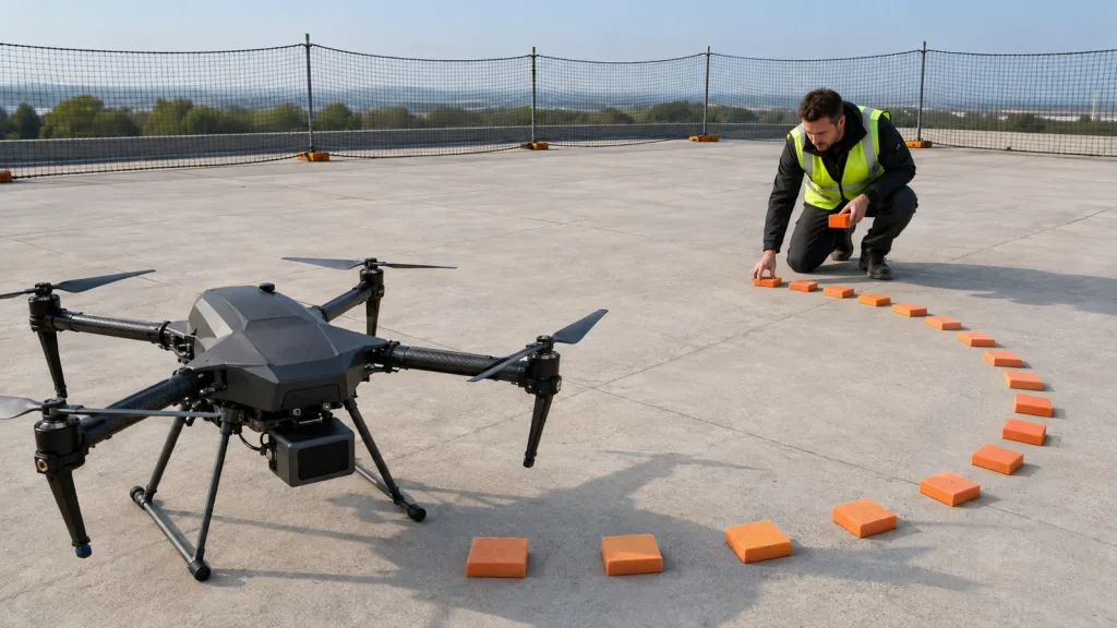
- Static angular sweep: move a measured target from forward-right through directly right to rear-right. Compare raw pixels, transformed rays, outgoing sectors, and controller sectors.
- Distance-step test: position a panel and thin pole at project-defined distances. Check minimum/maximum handling, accuracy acceptance, invalid states, and sector-edge behavior.
- Dropout and stale-data test: interrupt the stream in a safe bench setup. Confirm the controller transitions to the defined unknown/stale state instead of preserving a clear reading.
- Loaded transport test: run logging, autonomy, video, networking, and storage together. Measure rate, age, and jitter at the controller boundary.
- Managed low-speed lateral test: in a prepared area, approach a soft or non-damaging test target laterally under the approved procedure. Verify sensing evidence before judging behavior.
- Intended-mode test: repeat only in each flight mode that the requirements name. Record operator input, mode, controller state, sector data, and vehicle response on a shared timeline.
Autopilot behavior can be mode-specific. The official ArduPilot simple object-avoidance documentation, for example, distinguishes supported modes and configured avoidance behavior. Use the documentation for the actual firmware version, then verify on the actual vehicle. A controller-side right-sector display proves ingestion; it does not by itself prove braking or path modification.
If you also need the rear quadrant, use the separate backward obstacle-sensing validation guide. Treat each sector as its own chain before claiming combined coverage.
7. Where the MRP-LD1 Fits—and What Still Needs Engineering
The Featured MRP-LD1 Drone LiDAR Sensor is a compact SPAD dToF module whose listed applications include UAV obstacle avoidance and altitude hold. Its published interfaces and depth output can support evaluation of a side-looking perception path. The module is not described as a complete right-side avoidance system; mounting, calibration, message conversion, flight-controller configuration, dynamics, and validation remain system responsibilities.
| Published item | MRP-LD1 export value | Right-sector integration implication |
|---|---|---|
| Ranging principle | SPAD dToF; 940 nm VCSEL | Use the module’s depth output as perception input; validate target and environment performance. |
| Laser safety listing | Class 1 (FDA Recognized Eye-Safe) | Retain the exact supplied wording in project documentation; follow complete system handling requirements. |
| Published range | Indoor 0.5–25 m; outdoor 0.2–8 m | Set project limits only after testing actual right-side targets, angles, window, light, and integration. |
| Ambient-light specification | 80 klux | Plan bright-condition and incidence-angle tests; do not treat the value as guaranteed mission performance. |
| Published accuracy | 0.2–1 m: ≤±3 cm; 1–5 m: ≤±5 cm; 5–8 m: ≤±10 cm; 8–15 m: ≤±20 cm | Choose acceptance bands that stay within both the product envelope and the vehicle’s clearance budget. |
| Field of view | 60° H × 45° V | One module covers a bounded sector, not the entire right half-space or 360°. |
| Resolution and frame rate | 40 × 30 at 10 fps | Define pixel/ray mapping and then measure the end-to-end usable update age. |
| Interfaces | UART, UVC, UDP | Select the path that fits the compute architecture; verify packet framing, timestamps, loss, and recovery. |
| Platform support | Windows, ARM, Linux, Android | Confirm the exact driver, API, version, and target hardware during evaluation. |
| Electrical and mechanical | 5 V; 1.2 W; 8 g | Include connector, cable, mount, protection, thermal path, and power quality in the installed budget. |
| Temperature | Operating −20°C to 60°C; storage −30°C to 70°C | Validate the complete installation over the project’s required conditions. |
Interface choice should follow the data path. UVC may simplify early host visualization; UDP can fit a networked companion computer; UART may fit a compact serial architecture. None of those names alone establishes native compatibility with a particular flight controller. Ask for the current protocol and integration documentation, then budget conversion and validation work explicitly.
8. Worked Application: Lateral Inspection in a Service Corridor
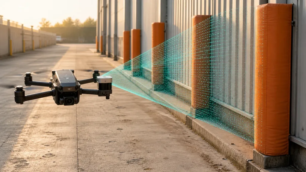
Illustrative engineering scenario—not customer results: a multirotor inspects assets along a service corridor and occasionally translates to aircraft-right to center a camera. Posts and a wall can enter the right side before they enter the forward view. The team wants a right-sector proximity input that can support a lateral-motion limit.
The team mounts one MRP-LD1 with its measured optical axis nominally toward aircraft-right. It records the final mount angles and surveys landing-gear occlusion. A matte panel is swept through the right sector to establish angle mapping; a thin vertical pole checks whether conservative binning preserves narrow obstacles. Each test capture contains the raw depth frame, transformed rays, output obstacle message, controller-side sector view, and synchronized timestamps.
Before flight, the team disconnects the stream during a props-off test and confirms that the controller changes the sector to the defined unavailable state. It then runs the complete compute load and measures message age and jitter. Only after these gates pass does the authorized team conduct a low-speed lateral trial with a soft target and a predeclared clearance rule.
The result of this process is not a generic claim that the aircraft “has right avoidance.” It is an evidence package tied to one hardware configuration, software version, mode, speed envelope, target set, and environment. Changes to the mount, window, payload, firmware, filter, or interface trigger the relevant regression tests.
For broader architecture choices around navigation and collision sensing, see Purpleriver’s UAV navigation and obstacle-avoidance solution overview.
9. Define Acceptance Evidence Before Flight
Write pass rules before looking at the data. That prevents a convenient graph from becoming an after-the-fact requirement. Numeric thresholds must come from the vehicle, operating envelope, risk process, and measured stack—not from a universal blog value.
| Gate | Minimum evidence package | Project-defined pass rule | Owner |
|---|---|---|---|
| Installed geometry | Mount drawing, photographs, yaw/pitch/roll, usable angular mask | Right-sector coverage and blind areas match the approved layout | Mechanical + perception |
| Depth validity | Raw captures across target, distance, angle, light, and attitude cases | Validity and error bands meet the application requirement | Perception |
| Angular transformation | Known target bearings compared across raw rays and output sectors | No sign, order, offset, or frame error within the declared tolerance | Software |
| Semantic integrity | Near, clear, unknown, out-of-range, and interrupted-stream cases | Every state maps to the documented controller state | Software + safety |
| Freshness | Acquisition-to-controller timestamps under representative load | Rate, age, jitter, and recovery remain within the approved budget | Embedded systems |
| Controller ingestion | Ground-station sector view and flight-controller log | Physical right target is visible only in the expected body sectors | Autopilot |
| Mode behavior | Mode, input, obstacle state, controller output, and vehicle motion timeline | Response meets the declared lateral operating envelope | Flight test |
| Regression | Configuration and software hashes plus rerun list | Relevant gates repeat after controlled changes | Systems engineering |
10. Common Right-Sector Integration Mistakes
- Calling a side-mounted module a right-avoidance system. The mount does not prove transformation, controller ingestion, or vehicle behavior.
- Using enclosure direction as optical-axis truth. Measure the installed optical frame and account for pitch, roll, and tolerances.
- Assuming equal-angle image columns. Use the actual calibration or documented projection.
- Averaging away narrow obstacles. Validate the aggregation rule with poles and sector-edge targets.
- Encoding missing data as clear. Preserve unknown, invalid, out-of-range, and stale semantics through every interface.
- Checking only the companion-computer display. Demand controller-side sector and log evidence.
- Using sensor fps as the latency claim. Measure age and jitter at the final consumer under representative load.
- Testing one attitude. Bank, pitch, landing gear, and payload geometry can move obstacles outside the usable vertical view.
- Inferring avoidance from detection. Verify the intended firmware version, configuration, mode, margin, and behavior.
- Claiming broad coverage from one FOV. Document the bounded sector and remaining blind areas explicitly.
11. RFQ and Evaluation-Sample Checklist
Give the supplier and internal teams a concrete integration question, not just “Will this work on a drone?” Include:
- aircraft type, intended right-side mounting location, and preliminary yaw/pitch/roll;
- required usable right-sector angles, distances, lateral speeds, target types, light, and weather envelope;
- landing gear, payload, protective-window, vibration, power, and thermal constraints;
- preferred UART, UVC, or UDP path and target host/flight-controller architecture;
- required pixel/ray calibration, invalid-value definitions, timestamp behavior, protocol details, and sample data;
- controller message type, body-frame convention, stale-data rule, and intended flight modes;
- acceptance targets for accuracy, dropout, angular mapping, rate, age, jitter, restart, and recovery;
- configuration control, software/document versions, change notification, and regression expectations.
A useful supplier response should let your team close the angle ledger and design a test. If a required field is unavailable, record the assumption and make it a bench-validation item rather than silently converting it into a product claim.
Plan the Right-Sector Evaluation Around Your Aircraft
Share your mounting envelope, target range, lateral speed, compute platform, interface preference, and flight-control stack. Purpleriver can help your team review the MRP-LD1’s published fit and define the questions for an evaluation sample—while keeping vehicle-level avoidance claims tied to your own integration evidence.