Quick answer: A drone collision avoidance sensor should be selected from the flight envelope backward. Start with approach speed, braking authority, pipeline delay, target types, light, weather, required directions, and the controller’s no-data behavior. Only then compare usable range, field of view, update rate, payload, power, and interface. A sensor supplies observations; the host computer and flight controller must turn those observations into a safe speed constraint, stop, or reroute command.
Define what the drone collision avoidance sensor must protect
“Avoid obstacles” is not a testable requirement. Write a mission statement such as: “Detect the defined wall, pole, cable-proxy, foliage, and vehicle targets early enough to limit a 2 m/s indoor inspection drone to the approved separation, across forward and lateral motion, with logged handling of invalid frames.” This sentence forces the team to name the target library, directions and control outcome.
Separate collision prevention from path planning. The current PX4 Collision Prevention documentation describes slowing or stopping a vehicle and maps sensor inputs into directional sectors. It also explains that missing directional data can restrict motion, depending on configuration. That is different from computing a new route around an object. Decide which outcome the project actually needs before buying hardware.
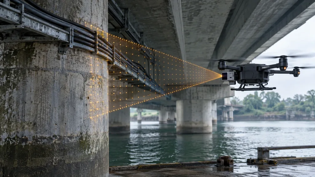
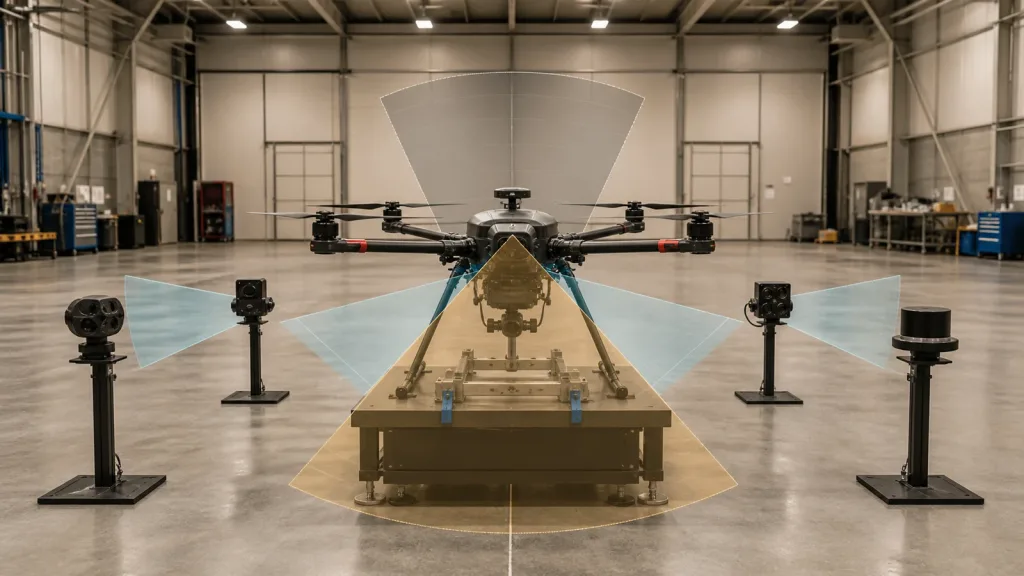
Coverage is three-dimensional. A wide horizontal FoV can still miss an overhead beam or a low diagonal cable. Plot the sensor frustum in the vehicle body frame, add pitch during acceleration and braking, then mark sectors hidden by landing gear, propellers, payloads, or the airframe. The site’s blind-sector and controller-handoff guide provides a useful companion method.
Score candidates against the operating envelope
| Gate | Evidence to request | Bench or flight acceptance test |
|---|---|---|
| Usable detection envelope | Range by target, illumination, angle, and minimum range | Measure valid-detection rate and error across the project matrix |
| Coverage | Horizontal/vertical FoV and orientation definition | Map occupied sectors after final mounting and aircraft pitch |
| Timing | Frame rate, timestamps, transport delay, stale-data behavior | Log sensor-to-command latency and consecutive invalid frames |
| Payload integration | Mass, voltage, power, connector, thermal limits | Weigh the installed chain and stress the power rail |
| Data contract | Depth format, units, invalid codes, frame convention, quality fields | Replay captured packets and inject malformed/stale samples |
| Host/control behavior | Driver ownership, obstacle map, speed limiter, stop logic | Prove the aircraft reaches the defined safe state |
| Environmental robustness | Ambient-light and target limits | Repeat with dark, bright, angled, partial, and moving targets |
Do not turn the scorecard into one weighted average too early. A module that fails a hard range, timing, coverage, power, or interface gate should not survive because it scores well on price or resolution. Keep “must pass” gates separate from preference scores.
Technology families also have different failure modes. Cameras can provide semantic detail but depend on scene texture and exposure; ultrasonic sensing can be useful at short range but has beam and material effects; radar can tolerate some visibility challenges but its angular detail and integration may differ; LiDAR measures active optical time of flight but must be qualified against reflectivity, incidence angle, ambient light, and occlusion. The existing comparison of collision-avoidance sensor types is a starting point, not a substitute for mission tests.
Treat the data path as part of the sensor
A depth module does not directly “avoid” anything. The complete chain is sensor exposure → depth output → transport → parser → coordinate transform → temporal filter → obstacle sectors → flight constraint. Every arrow adds delay and a possible fault. Define units, minimum and maximum valid values, invalid codes, timestamps, sensor orientation, FoV, and freshness limits before flight.
The MAVLink DISTANCE_SENSOR definition includes orientation, minimum and maximum distance, FoV, covariance and signal quality fields; OBSTACLE_DISTANCE represents angular distance bins. A depth array normally needs host-side reduction or mapping before it can populate those messages. Document whether the closest valid pixel, a percentile, clustered obstacle, or another rule controls each sector. The nine-field LiDAR data-contract checklist helps make that handoff reviewable.
Also define no-data behavior. A stale last-good range must not masquerade as a current clear path. Test packet loss, frozen timestamps, all-invalid frames, partial FoV dropout, sensor reboot, and host restart. The safe response may be a speed cap, hover, stop, pilot warning, or mission abort; it depends on the aircraft and operating concept.
Evaluate a compact dToF candidate without overstating it
The Featured MRP-LD1 drone LiDAR sensor is one compact candidate for a host-integrated depth pipeline. Its published fields are shown below. These are component specifications, not proof of collision-avoidance performance on a particular aircraft.
| Verified product field | MRP-LD1 published value | Integration meaning |
|---|---|---|
| Ranging principle | SPAD direct time of flight (dToF) | Produces depth measurements; avoidance decisions remain in the host stack |
| Emitter | 940 nm VCSEL | Include target and sunlight tests at the actual mounting geometry |
| Depth output | 40 × 30 at 10 fps | Treat it as a depth grid, not as a single guaranteed stop signal |
| Field of view | 60° horizontal × 45° vertical | Map the mounted FoV into vehicle sectors and document uncovered directions |
| Published range | Indoor 0.5–25 m; outdoor 0.2–8 m | Keep indoor and outdoor envelopes separate; qualify usable range by target and light |
| Ambient-light resistance | 80 klux | A specification to test under a defined matrix, not permission to skip bright-scene validation |
| Interfaces | UART, UVC, UDP | Select a transport that the host can timestamp, parse, health-check, and replay |
| Power and mass | 5 V, 1.2 W, 8 g | Budget regulator, cable, mount, compute, and protection in addition to the module |
| Software support | Windows, ARM, Linux, Android | Confirm the required SDK build and data path on the target computer |
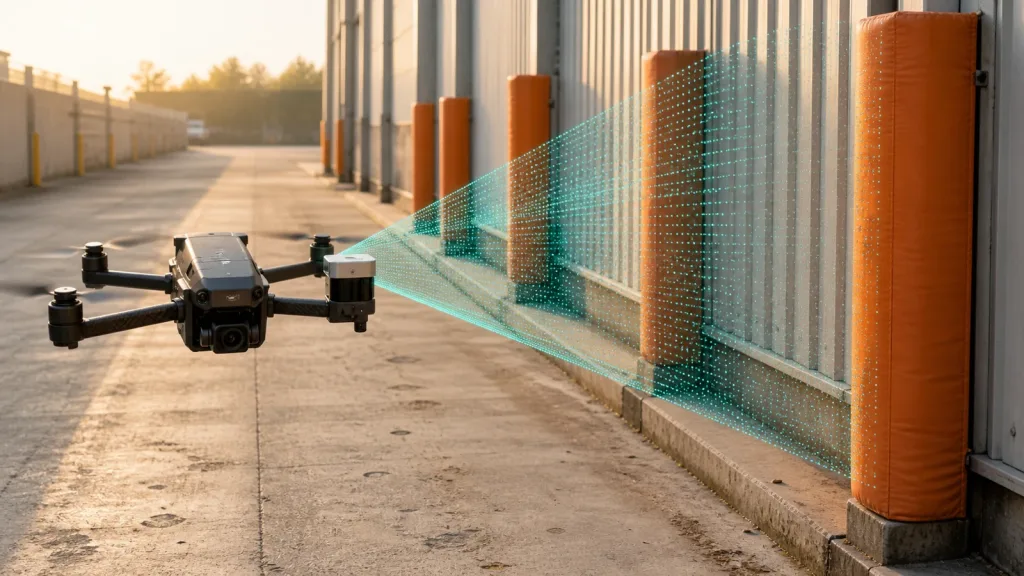
At 60° × 45°, one forward-facing module covers a defined frustum, not the whole airframe. At 10 fps, new frames are nominally separated by 0.1 seconds before transport and processing. The team still has to validate the end-to-end delay, usable distance for its targets, mounting vibration, optical window, airflow, EMI, regulator behavior, and flight-controller interface.
Use a gated bench-to-flight trial
Worked evaluation scenario—not a customer result
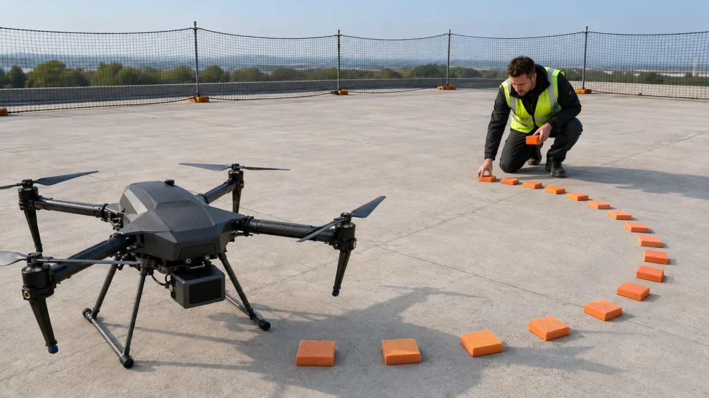
Consider an indoor multirotor intended to move at up to 2 m/s in a warehouse inspection aisle. The target set includes a painted wall, rack upright, angled carton, dark fabric panel, and a thin pole proxy. The team mounts one forward sensor, measures its actual frustum, and discovers that yawed flight exposes a lateral gap. Instead of claiming success from straight approaches, it adds a side-sector requirement and caps speed until coverage is expanded.
Bench tests first log depth, invalid pixels, timestamps, parser output, obstacle bins, commanded velocity, and vehicle state. Tethered tests then use a soft obstacle and increasing speeds. Free flight begins only after stale-data and sensor-disconnect injections produce the approved safe behavior. This evidence is more useful than a video of one successful stop.
- Freeze the target/lighting/distance matrix and pass criteria.
- Validate raw depth and packet integrity on the bench.
- Measure end-to-end latency using synchronized logs.
- Map mounted coverage and occlusions.
- Inject invalid, delayed, frozen, and missing data.
- Run restrained motion tests with soft obstacles.
- Expand speed and geometry only after the previous gate passes.
Common selection mistakes
- Buying by maximum range: published maximum and operational usable range are different quantities.
- Ignoring minimum range: a close obstacle can enter an unmeasured zone before the aircraft stops.
- Counting the module but not the chain: regulator, cabling, mount, compute, optical protection, and software add mass and risk.
- Treating all returns equally: dark, angled, small, wet, or sunlit targets may produce different valid-data behavior.
- Using the last good sample forever: freshness and invalid-state rules must be explicit.
- Testing only head-on hover: translate, yaw, pitch, brake, and fly near sector boundaries.
RFQ and engineering-sample checklist
- Mission speed, deceleration assumptions, separation margin, and required directions.
- Target library, reflectivity/finish notes, target size, approach angle, illumination, and weather.
- Range/FoV/update-rate evidence and definition of invalid output.
- Installed mass, voltage, steady/transient power, connector, cable, mount, and optical window.
- Interface protocol, timestamps, coordinate frame, units, quality fields, and sample recordings.
- Host platform, flight stack, driver owner, message mapping, and safe-state owner.
- Bench, tethered, and flight acceptance criteria plus log retention.