LiDAR sensor pages often fail engineering teams because they collapse everything into one promise: more range, more points, more safety. That is not how pilot programs fail in practice. A compact module is approved too early when the team has not yet proved four things on the real host: whether the depth data is usable at the intended stand-off distance, whether low-altitude control modes receive valid distance data when they need it, whether the interface path is debuggable, and whether the payload and power budget still make sense after mounting.
For Purpleriver's current Featured product, the verified facts are concrete. The MRP-LD1 is a solid-state SPAD dToF module with a 940 nm VCSEL, Class 1 FDA-recognized eye safety, indoor range of 0.5 m to 25 m, outdoor range of 0.2 m to 8 m, 80Klux ambient-light resistance, 60° × 45° field of view, 40 × 30 output at 10 fps, UART/UVC/UDP interfaces, 5 V input, 1.2 W power draw, and 8 g weight. Those facts are enough to build a serious shortlist, but not enough to approve a pilot build without workflow-level validation.
Quick Answer
| What makes a compact LiDAR sensor pilot-ready? | It must deliver usable depth behavior in the mission distance band, provide valid host data in the control modes that matter, fit the payload and power budget after mounting, and preserve a clean debug path. |
|---|---|
| What should buyers verify before comparing vendors? | Depth usefulness, low-altitude validity window, field of view on the real host, interface handoff, ambient-light tolerance, and mounted-state practicality. |
| What is the most common buying mistake? | Choosing from the spec sheet alone and discovering too late that the integration path, usable distance window, or host geometry breaks the pilot workflow. |
Why a Spec Sheet Does Not Approve a LiDAR Sensor
A pilot program rarely fails because the module had no maximum-range number. It fails because the number did not answer the real engineering question. NIST's April 27, 2026 publication on depth resolution defines the problem more usefully: the team must know the smallest physical depth change that produces a detectable change in measured depth. In other words, the first proof target is not marketing range. It is whether the sensor can resolve the depth behavior the application actually needs.
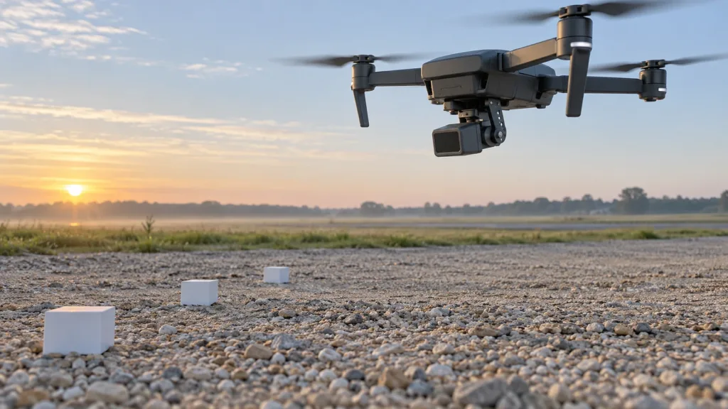
That distinction matters in compact UAV and robotics work. PX4's current documentation shows that distance sensors are operationally relevant for terrain following, terrain hold, improved landing behavior, and collision prevention. ArduPilot's current surface-tracking documentation shows that pilot-controlled low-altitude behavior depends on a downward rangefinder actually seeing the ground. If the sensor stops giving valid data where the workflow still needs it, the module is not ready no matter how good the top-line specification looked in procurement.
For a buyer or integration lead, the screening question becomes simple: does the module produce useful, valid, and debuggable depth data in the exact geometry and control loop that the pilot build will use?
LiDAR Sensor Decision Table for Pilot-Build Screening
| Criterion | Approve for deeper evaluation if... | Do not shortlist yet if... |
|---|---|---|
| Usable depth behavior | The module shows stable, interpretable depth changes in the real mission distance band. | The team only knows maximum range and cannot explain useful depth change at the working stand-off. |
| Low-altitude validity window | Control logs confirm valid distance data wherever terrain hold, hover support, or close-ground logic depends on it. | The host leaves valid sensor data before the control workflow is finished. |
| Field of view on the host | The mounted FoV covers the needed ground patch or obstacle corridor without being blocked by airframe or chassis geometry. | Brackets, landing gear, prop guards, or body panels shadow the critical view. |
| Interface handoff | The team can capture, replay, and diagnose data over the intended interface. | The module demos live output but leaves no clean failure-analysis path. |
| Environmental robustness | Light, target reflectivity, and surface variation stay inside a validated operating envelope. | The system has not been checked under the actual outdoor or mixed-surface conditions expected in the pilot. |
| Payload and power fit | Mass, wiring, and power draw still fit the finished host after mounts and cable routing are added. | The raw module fits on paper but the integrated assembly breaks the host budget. |
What the MRP-LD1 Facts Mean in Practice
The current Featured product is the LiDAR Drone Module – MRP-LD1 Solid-State dToF Sensor. The export lists a solid-state SPAD dToF architecture, 940 nm VCSEL, Class 1 FDA-recognized eye safety, indoor 0.5 m to 25 m range, outdoor 0.2 m to 8 m range, 80Klux ambient-light resistance, 40 × 30 output at 10 fps, a 60° × 45° field of view, and UART/UVC/UDP interfaces.
| Exact exported fact | Shortlist implication |
|---|---|
| Outdoor range 0.2 m to 8 m | Useful for close-ground and short-to-mid standoff work, but it must be validated against the real control window rather than treated as a universal obstacle range promise. |
| 40 × 30 output at 10 fps | Enough to support pilot-stage checks of depth behavior and host handoff, but the team should still prove that the spatial and temporal output matches the decision loop they intend to run. |
| 60° × 45° FoV | Wide enough to be useful on compact hosts, yet still worth checking after mount because brackets and body geometry can change the actually usable patch. |
| UART / UVC / UDP | Gives multiple integration paths so the team can prioritize whichever path best supports capture, replay, and controller handoff. |
| Ambient-light resistance 80Klux | Supports outdoor evaluation, but should still be checked under the actual glare and shadow conditions expected in the pilot route. |
| 5 V, 1.2 W, 8 g | Strong compact-host fit on paper, especially for small UAV or lightweight robotics builds, but the final mounted assembly remains the real approval point. |
| Application scope includes UAV altitude hold, obstacle avoidance, and robot navigation | Makes the module relevant to both aerial and ground pilot programs without guaranteeing success in either one unless the host workflow is validated. |
Validation Workflow Before a Compact Module Enters a Pilot Build
1. Define the single decision the sensor must support
Do not begin with a generic requirement like “better perception.” Decide whether the first pilot needs hover support, terrain-follow aid, close-range obstacle awareness, robot docking protection, or a replayable engineering data path. One module can support several jobs, but the approval test needs one primary pass/fail question.
2. Test useful depth change, not just maximum range
Use a stepped target or known-height ladder to prove whether the reported depth changes are useful at the actual stand-off distance. This is where the NIST depth-resolution framing matters. If the sensor cannot show meaningful change at the working distance, the pilot team does not yet have a usable measurement tool.
3. Validate the mounted field of view
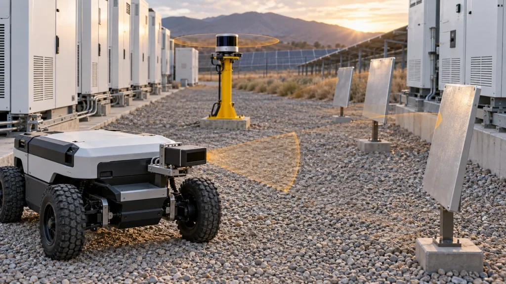
Bench-level FoV is not the same as airframe or chassis FoV. On a quadrotor, landing gear and belly plates can shadow the patch you care about. On a small robot, bumper edges and sensor recesses can hide the corridor edges. Re-run the target check after the final bracket and cable routing are installed.
4. Prove the valid-data window in the real control mode
Current PX4 and ArduPilot guidance both point to the same engineering reality: the host only benefits when the distance sensor remains valid in the operating band where the controller expects it. That means a low-altitude test is not optional for close-ground UAV behavior, and a real corridor or docking-height test is not optional for small robots.
5. Preserve a debug path before the first outdoor run
Pick the interface that makes failure visible, not just the one that makes a demo easy. A pilot build is far more valuable when the team can replay a bad run and explain what the sensor sent, what the host interpreted, and where the handoff broke.
Interface, Host Handoff, and Control-Mode Checks
Integration is where many compact-module programs stall. The same sensor can look excellent in isolation and still fail because the host cannot consume or diagnose the data path cleanly.
| Integration layer | What to verify |
|---|---|
| Raw data transport | Whether UART, UVC, or UDP gives the cleanest path for the host and the best chance of replay after a failed run. |
| Controller expectation | Whether the host control mode actually uses the incoming distance data where the team expects it to matter. |
| Mount and geometry | Whether the final bracket, cable strain relief, and host bodywork change the usable FoV or vibration path. |
| Operational environment | Whether the module stays reliable under the same glare, texture, and motion pattern that the pilot route will impose. |
PX4's current optical-flow documentation specifically expects a downward-facing distance sensor and recommends LiDAR over sonar for robustness and accuracy. That matters for UAV teams because it reframes the purchase decision. The right compact sensor is not just a rangefinder. It is part of a control stack.
If the team cannot yet explain what the host does when distance data becomes invalid, the shortlist is incomplete. The unresolved question is a system-risk item, not a tuning detail.
Example Case: One Module, Two Pilot Hosts
Imagine an engineering team that wants to use one compact sensor platform for two early pilots: a low-altitude infrastructure-inspection quadrotor and a small indoor robot that must move through narrow service corridors. The same module does not need to solve both jobs identically, but it must clear the same shortlist logic.
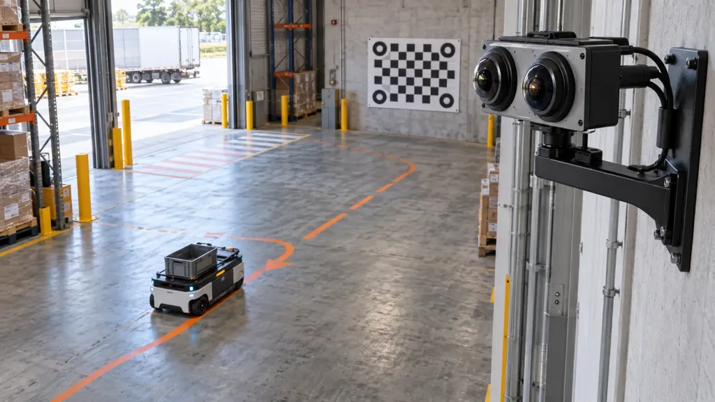
For the quadrotor, the critical proof is whether the module supplies usable low-altitude distance data after the final belly mount is installed and whether the aircraft still sees the intended ground patch across the full hold band. For the robot, the proof is whether the mounted FoV covers the near-field corridor and whether the host can interpret the data path reliably during slow approach and stop behavior.
The decision is not “can this sensor output depth?” The decision is “does this sensor still deliver useful, valid, and diagnosable depth once each real host imposes geometry, motion, and interface constraints?” That is the approval threshold a pilot build should use.
Common Mistakes
- Ranking candidates by maximum range without proving useful depth change at the working stand-off.
- Assuming the mounted field of view will match the bench-level field of view.
- Approving a module before the team has logged what happens when valid distance data drops out.
- Choosing the easiest demo interface instead of the most diagnosable host-handoff path.
- Treating payload mass and power draw as solved before brackets, harnesses, and strain relief are added.
- Using one clean indoor demo as evidence for an outdoor or mixed-environment pilot.
RFQ and Evaluation Checklist
| Checklist item | What to confirm |
|---|---|
| Primary job | The team has named the exact first decision the sensor must support: hover, terrain aid, docking, obstacle buffer, or data replay. |
| Useful depth proof | The module has been tested against known target steps in the actual mission distance band. |
| Mounted FoV proof | The final host geometry does not block the critical patch or corridor. |
| Valid-data window | The host still receives valid distance information in the control band where the pilot needs it. |
| Interface replay | The chosen transport path lets the team capture and diagnose bad runs. |
| Integrated payload fit | Mass, wiring, voltage, and mount hardware still fit after the final assembly is complete. |
| Field-condition proof | The shortlist has been checked under the actual light, surface, or corridor conditions expected in the pilot. |
Need a Compact LiDAR Sensor Shortlist That Survives Real Integration?
Start with the control workflow and the mounted geometry, not the vendor headline. Review the MRP-LD1 product page, compare it with your real sensing requirements, and use Purpleriver's documentation resources before you approve a pilot build.