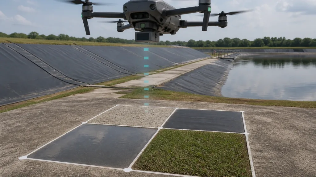
Downward Vision System approval usually fails for one reason: teams prove a clean hover over one friendly surface and then assume the same positioning workflow will behave the same way above dark membrane, shallow water, monochrome paint, or weak-texture ground. That assumption is risky because current OEM and autopilot guidance makes clear that vision-based low-altitude behavior depends on surface conditions and, in many controller workflows, on valid range data as well.
For Purpleriver's current Featured product, the usable facts are specific: the MRP-LD1 is a solid-state SPAD dToF module with 940 nm VCSEL, Class 1 FDA-recognized eye safety, indoor range of 0.5 m to 25 m, outdoor range of 0.2 m to 8 m, ambient-light resistance to 80Klux, 60° × 45° field of view, 40 × 30 output at 10 fps, UART/UVC/UDP interfaces, 5 V input, 1.2 W power draw, and 8 g weight. Those facts do not turn a vision-only hover workflow into a safe one by themselves, but they do make the module relevant when a UAV team needs a more dependable low-altitude support path than downward vision alone.
Quick Answer
| When is a downward vision workflow ready for field use? | Only after the aircraft has been tested across the real surfaces, lighting, and altitude band expected in the mission, with clear proof of how the controller behaves when vision quality or range support drops. |
|---|---|
| When should a team add LiDAR support? | When the route includes dark, reflective, transparent, weak-texture, or mixed-surface ground, or when the controller requires valid range data for stable low-altitude vision-based positioning. |
| What is the most common approval mistake? | Signing off after one smooth indoor or dry concrete hover without testing the surface and light combinations that actually break downward vision confidence. |
Why a Downward Vision System Passes One Hover and Fails the Next Surface
Current DJI support guidance warns that vision systems may not work properly over extremely dark surfaces, water or transparent surfaces, monochrome surfaces, or surfaces without clear patterns or texture. That warning is operationally important because many low-altitude UAV routes include exactly those ground conditions: pond liners, wet concrete, shadowed asphalt, polished coatings, or sparse texture at dawn and dusk.
Controller documentation adds a second layer. Current PX4 EKF2 guidance states that optical-flow data is used only when valid rangefinder data is available, while current ArduPilot documentation for HereFlow notes that a rangefinder is required for autonomous modes such as Loiter and RTL. In other words, some low-altitude workflows are not just a camera problem. They are a combined vision-plus-range validation problem.
This is why a simple indoor hover is a weak acceptance test. The real approval question is not whether the aircraft can hover over one safe patch. It is whether the team understands how the positioning stack behaves as surface texture, reflectivity, light, and valid altitude-support data change under the aircraft.
Decision Table: When Vision-Only Is Not Enough
| Condition to validate | Vision-only may be acceptable if... | LiDAR support is strongly recommended if... |
|---|---|---|
| Textured dry concrete or compact asphalt | Hover quality is stable and the controller does not lose confidence in the expected altitude band. | The route later changes to very different ground materials or higher glare. |
| Dark or monochrome ground | Only after repeatable proof in the actual lighting band. | The team has not reproduced confidence on dark or low-feature surfaces. |
| Shallow water, glossy coatings, or reflective patches | Rarely. These are exactly the surfaces official OEM guidance flags as problematic. | The route includes puddles, pond edges, solar-table glare, or polished floor sections. |
| Mixed-surface transitions | Only if the aircraft keeps stable position while crossing all patches in sequence. | Position quality changes at each transition or the team cannot explain the change. |
| Autonomous or low-intervention modes | Only after the controller's dependence on valid range data is fully logged and understood. | The autopilot documentation for the chosen stack expects range support for the mode you plan to use. |
| Low-light operation | Only with real low-light proof on the target surface set. | The mission starts or ends in poor light, shadow, or uneven illumination. |
What the MRP-LD1 Facts Change for a Downward Vision System Workflow
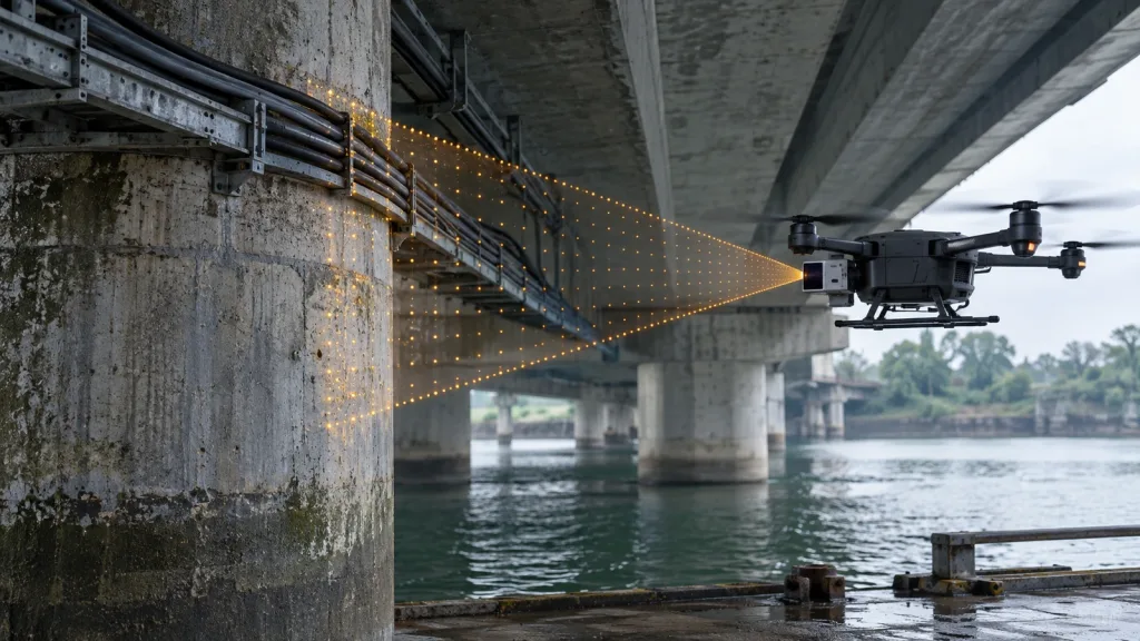
The current Featured product is the LiDAR Drone Module – MRP-LD1 Solid-State dToF Sensor. The export lists solid-state SPAD dToF architecture, 940 nm VCSEL, Class 1 FDA-recognized eye safety, indoor 0.5 m to 25 m range, outdoor 0.2 m to 8 m range, 80Klux ambient-light resistance, 40 × 30 output at 10 fps, 60° × 45° field of view, and UART/UVC/UDP interfaces.
| Exact exported fact | Why it matters when downward vision is the weak link |
|---|---|
| Outdoor range 0.2 m to 8 m | Gives the team a defined low-altitude support window to validate against the controller's range-data requirements. |
| Ambient-light resistance 80Klux | Useful when the failure driver is bright outdoor light or mixed shadow, which often hurts vision confidence before it hurts LiDAR support. |
| 40 × 30 output at 10 fps | Enough to evaluate whether the support path is fast and spatially rich enough for close-ground stability checks, without inventing guarantees the export does not state. |
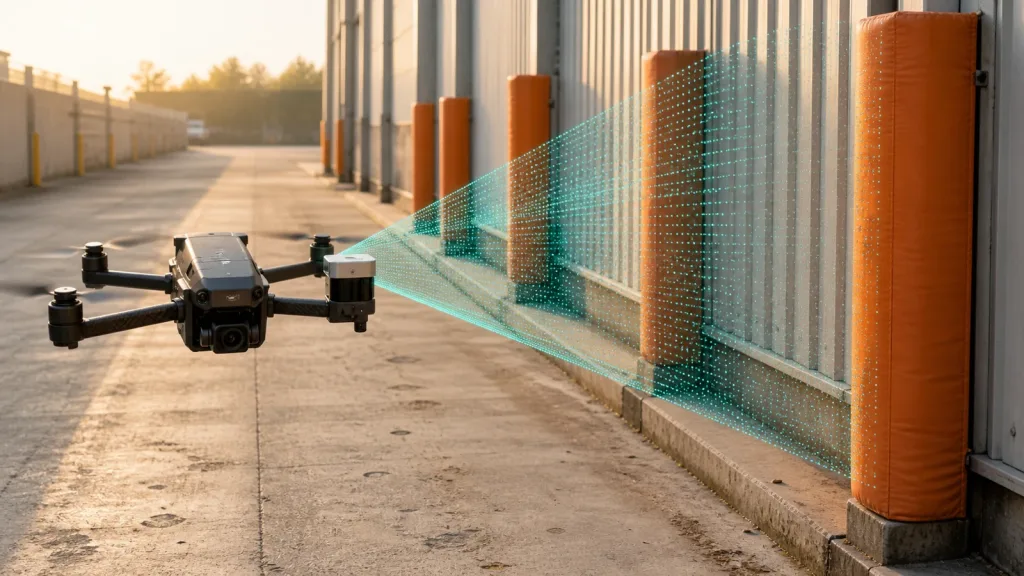
| 60° × 45° FoV | Helps the team check how much of the ground patch is actually seen under the aircraft during a mixed-surface crossing. |
| UART / UVC / UDP | Lets the team choose the cleanest debug path for a flight controller or companion computer when diagnosing vision-support failures. |
| 5 V, 1.2 W, 8 g | Keeps the support module practical for compact UAV integration without claiming that low payload automatically equals stable positioning. |
| Application scope includes UAV altitude hold and obstacle avoidance | Supports the relevance of testing this module as a low-altitude support sensor when a downward vision workflow needs stronger ground-reference confidence. |
Validation Workflow Before Low-Altitude Flight Approval
1. Define the exact role of the Downward Vision System
Start by naming the job precisely: hover stabilization, position hold, optical-flow support, terrain-proximate flight, landing improvement, or a combined workflow. If the team cannot state the controller role, the test plan is too vague to approve.
2. Build a surface matrix instead of one demo pad
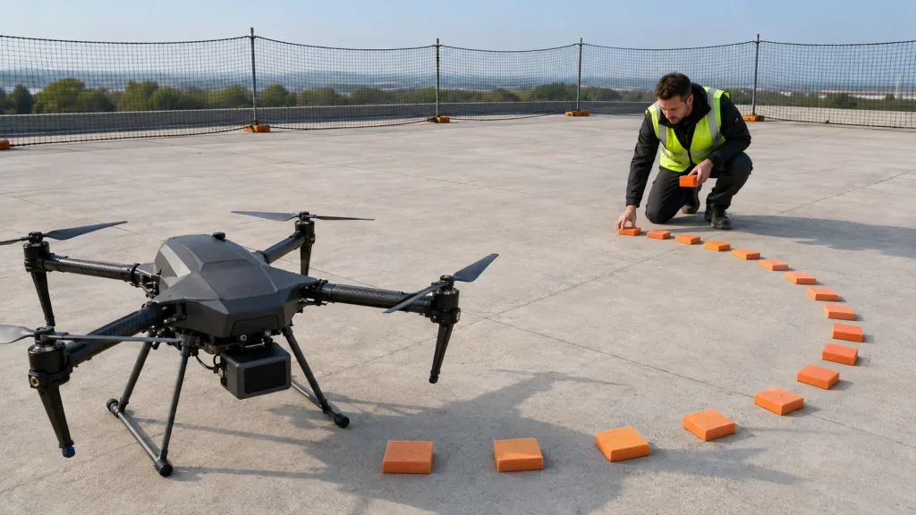
Create a short, safe validation lane with at least four ground conditions that match real operations: textured concrete, dark matte material, reflective wet patch, and a natural-texture section such as grass or gravel. The aircraft should prove stable behavior over every patch, not just the easiest one.
3. Repeat the lane in the real lighting band
A pass at mid-morning does not prove a pass at first light, heavy shadow, or backlit conditions. If the mission environment changes by time of day, repeat the lane under the same lighting band the pilot team expects in the field.
4. Prove the controller's range-data dependence
PX4 documents that optical-flow data is fused only when valid rangefinder data is available, and ArduPilot documents that autonomous optical-flow use requires a rangefinder in the relevant modes. That means the approval test must include a controlled check of what happens when valid range support is present, degraded, or lost.
5. Log the mounted system, not just the raw sensor
Repeat the validation after final mount, cable routing, and landing-gear placement are complete. A vision-and-LiDAR stack that looks stable on a bench can still fail once the belly mount changes the field of view or vibration path.
Interface, Range Data, and Controller Handoff
Low-altitude positioning failures are often integration failures. The approval package should document three layers together.
| Layer | What to verify |
|---|---|
| Surface perception | Whether the aircraft stays stable over dark, reflective, transparent, and low-texture ground rather than only over a friendly test patch. |
| Range support | Whether the controller sees valid altitude-support data throughout the target low-altitude band. |
| Debug path | Whether UART, UVC, or UDP gives the clearest capture and replay path after a failed run. |
Current PX4 optical-flow guidance recommends LiDAR rather than sonar because of robustness and accuracy. That is useful for teams deciding how to support a downward vision workflow when the route includes low-feature or reflective surfaces. It does not eliminate the need for testing, but it does justify a stricter sensor-choice standard than a quick indoor vision-only demo.
If the team still cannot explain when the controller trusts vision, when it requires range support, and what happens when either weakens, pause the program and review the stack before pilot deployment. The missing explanation is a system risk, not an editorial detail.
Example Case: Retention-Pond Embankment Inspection
Imagine a compact quadrotor inspecting a retention-pond embankment after rain. The route begins over textured concrete, crosses a black geomembrane liner, passes a shallow reflective puddle, and finishes beside short grass. This is a realistic path for a low-altitude maintenance or infrastructure survey, and it is exactly the kind of route that exposes the limits of a downward-vision-only approval.
The team should ask five questions before flight sign-off:
- Does the aircraft remain stable above every surface patch, not just the concrete start point?
- What changes when the vehicle crosses from textured ground to dark or reflective material?
- Does the autopilot still have valid range support across the whole low-altitude band?
- Can the team identify the exact point where confidence degrades or fallback occurs?
- Can the logged data explain the event after the run?
If any answer is still uncertain, the route is not ready for operational low-altitude work, even if the first hover looked smooth.
Common Mistakes
- Approving the workflow after one indoor or dry-surface hover.
- Ignoring the exact surfaces official OEM guidance already flags as problematic for vision systems.
- Assuming optical flow is independent of valid range support in the chosen controller stack.
- Adding a LiDAR module without re-running the full mounted-airframe validation lane.
- Choosing a sensor interface that is easy to demo live but poor for replay and failure diagnosis.
- Confusing a stable video view with stable low-altitude position confidence.
RFQ and Evaluation Checklist
| Checklist item | What to confirm |
|---|---|
| Role definition | The team knows whether the downward vision workflow is supporting hover, position hold, optical flow, or a hybrid low-altitude stack. |
| Surface matrix | The aircraft has been tested over all real mission surface types, including dark and reflective sections. |
| Lighting band | The proof run matches the actual daylight or low-light conditions expected in deployment. |
| Range-support proof | The controller's dependence on valid range data is logged and understood in the intended altitude band. |
| Mounted-state proof | The full stack has been retested after final mount, cable routing, and landing-gear placement. |
| Debug path | The team can capture and replay the event through the chosen integration interface. |
| Approval gate | No field deployment is approved until all six items above are documented. |
Need Better Low-Altitude Confidence Than Vision Alone?
Start with exact ground-truth testing, then decide whether your route needs a dedicated LiDAR support path. Review the MRP-LD1 product page, compare it with your real UAV sensing requirements, and use Purpleriver's documentation resources before approving low-altitude flight over mixed surfaces.