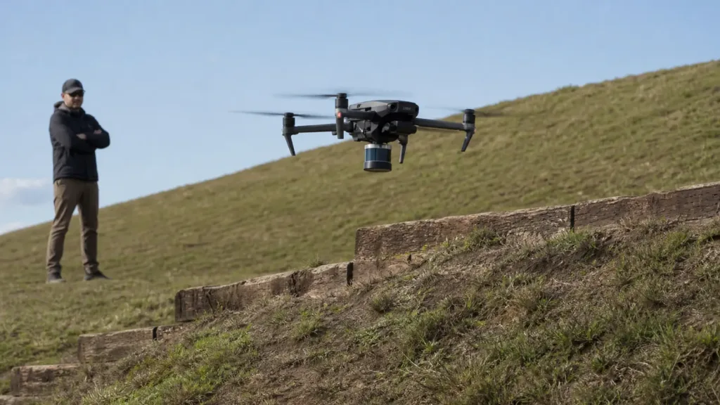
drone altitude hold LiDAR becomes useful when a UAV team stops treating low-altitude control as a simple barometer problem and starts testing what actually happens over uneven ground, rotor wash, and short-range obstacles. The engineering question is not whether a LiDAR module can report distance on a bench. It is whether the aircraft can keep a believable hover band, hold clearance during descent, and fail safely when the terrain or signal changes.
This guide is written for UAV integration engineers and technical buyers who need a practical validation workflow before they connect a compact dToF module to a flight controller, companion computer, or field-test program.
| Quick answer | Validate drone altitude hold LiDAR by defining a low-altitude hold band, logging real terrain-follow runs, checking fallback behavior above sensor range, and proving the data path works before you trust the module in flight tests. |
|---|---|
| Best fit | UAV teams evaluating downward-looking LiDAR support for low-altitude hold, terrain following, descent control, or hover stability over uneven ground. |
| Decision rule | If the team cannot define the usable altitude band, controller handoff, and reject conditions for dropouts or terrain transitions, the LiDAR module is not ready for flight integration. |
Why drone altitude hold LiDAR needs a different validation workflow
Official flight-stack guidance already hints at the right mindset. PX4 documents distance sensors and terrain hold as low-altitude aids for terrain following, precision hovering, and improved landing behavior, while also keeping the feature scoped to vehicles that actually have a supported distance sensor and a defined mode workflow. ArduPilot makes the same system point from the other direction: downward-facing rangefinders are used in height-control modes only within their usable range, and after that the controller falls back to the barometer.
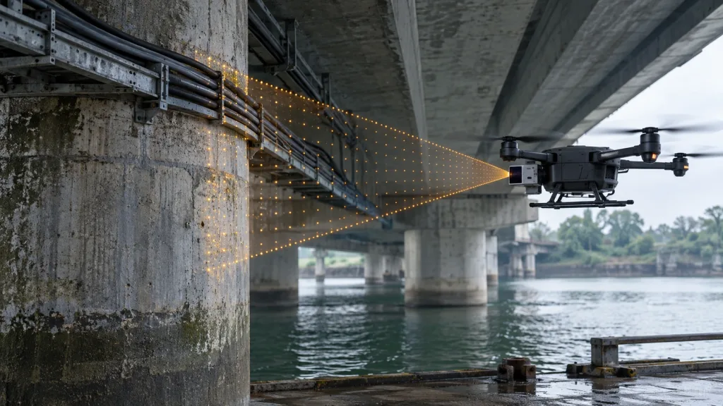
That means a compact LiDAR module should be validated as part of a control chain, not as an isolated sensor demo. A UAV team needs to know four things before trusting it: the usable altitude band, the terrain types that break confidence, the exact handoff when the aircraft exceeds sensor range, and the logging path that lets weak runs be replayed instead of guessed from memory.
If you need the broader sensor background first, Purpleriver already covers what drone LiDAR means for UAV integration teams. This article starts later in the workflow: validating a drone altitude hold LiDAR setup for actual low-altitude control support.
Decision matrix for low-altitude control support
| Evaluation area | What to verify | Why it matters in altitude hold work | Reject if |
|---|---|---|---|
| Usable altitude band | Minimum and maximum effective distance for the intended hover and descent envelope | The controller can only rely on LiDAR inside the band where returns stay believable | No one can state where the sensor should be trusted and where the barometer takes over |
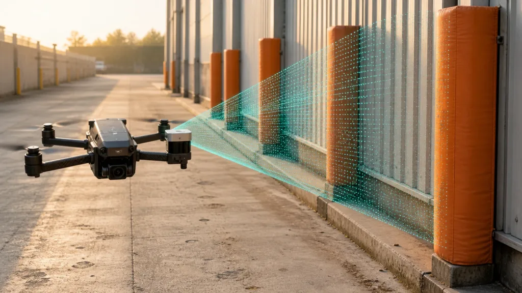
| Terrain transition behavior | Grass, dirt edges, retaining walls, slope changes, and partial occlusions during low flight | Altitude hold errors often appear at terrain breaks rather than on flat test pads | The test set contains only flat indoor or paved surfaces |
| Controller handoff | Mode behavior when the aircraft rises above rangefinder limits or loses reliable returns | Low-altitude hold is safe only if fallback is understood before field tests | Fallback logic is unknown or only inferred from one successful hover |
| Data path | How range, depth, and timing evidence are logged and replayed | Weak hovers and step responses must be debuggable after the flight | The team cannot align sensor output with controller events |
| Program fit | Power, weight, interface, mounting angle, and host support | A usable altitude-hold sensor still fails if it creates integration friction the UAV team cannot support | Bring-up requires undocumented tools or unstable mounting |
Exact featured-product parameters to validate
The current Featured product for this workflow is the LiDAR Drone Module - MRP-LD1 Solid-State dToF Sensor. The export explicitly lists UAV obstacle avoidance, altitude hold, and terrain following among its supported application scopes, so it is the correct factual product basis for this article.
| Parameter | Published value | Validation implication |
|---|---|---|
| Ranging principle | dTOF | Plan for depth-oriented logging and timing checks instead of treating it like a simple sonar replacement. |
| Scanning principle | SPAD | Use scene evidence to validate performance; do not turn the integration review into a detector-only discussion. |
| Emitter | 940nm VCSEL | Include daytime ground tests and surface changes that may affect return behavior. |
| Laser safety | Class 1 | Useful for screening, but operating procedures and aircraft integration still need their own review. |
| Range | Indoor 0.5-25m; outdoor 0.2-8m | For altitude hold, validate the real outdoor hover band rather than the headline indoor number. |
| Ambient-light resistance | 80Klux | Midday or bright-sky tests belong in the acceptance plan if the aircraft flies outside. |
| Accuracy | 0.2-1m <= +/-3cm; 1-5m <= +/-5cm; 5-8m <= +/-10cm; 8-15m <= +/-20cm | Translate each band into hover-margin, descent, and terrain-clearance limits. |
| FoV | 60 degrees (H) x 45 degrees (V) | Check that the downward mount still covers the terrain profile that matters during pitch changes. |
| Resolution / frame rate | 40 x 30 at 10fps | Enough for many low-altitude support tasks if the controller logic does not assume dense mapping output. |
| Interfaces | UART / UVC / UDP | Choose the fastest path to repeatable logs before optimizing the final architecture. |
| Software support | Windows / ARM / Linux / Android | Useful when the bench logger and the onboard computer are not the same system. |
| Power / weight | 5V, 1.2W, 8g | Helpful for compact UAV payload budgets, but still verify cable routing and mount stiffness. |
Bench-to-field workflow before controller trust
1. Define the hold band before the first hover
Write down the exact altitude band where LiDAR support is supposed to help. For example: a near-ground hover band for terrain following, a controlled descent band for landing, or a short-range buffer over uneven crop rows or embankments. That definition should include the expected controller fallback once the aircraft exceeds the rangefinder's usable distance.
2. Start with the simplest replayable interface path
The MRP-LD1 supports UART, UVC, and UDP. The first milestone is not elegance. It is replay. Use the interface that gets you synchronized sensor evidence fastest, then refine the architecture later. Purpleriver's documentation hub, sample datasets, and interface guide on UART, UVC, or UDP are the right internal starting points.
3. Force terrain changes into the first validation run
Flat surfaces rarely expose the real problem. The first outdoor validation should include a stepped edge, sloped ground, rough grass, or a transition between different ground textures. That is where a drone altitude hold LiDAR setup proves whether it can maintain a believable clearance band instead of merely reporting a clean number on a uniform pad.
4. Check mode transitions, not just stable hover
PX4 terrain hold documentation and ArduPilot rangefinder guidance both imply a mode-aware workflow: the distance sensor is helpful only within a defined operating context. So review takeoff, climb-out above rangefinder limits, return into the hold band, and descent. A one-point hover test does not prove integration readiness.
5. Freeze reject conditions before expanding the flight envelope
Reject the setup if the sensor drops out unpredictably across terrain steps, if the altitude band cannot be explained after replay, if fallback timing is unclear, or if the mount geometry lets landing gear or pitch angle hide the useful view. The right time to discover that is before a larger field trial, not during it.
Interface, data, and integration planning
Low-altitude control support fails more often in the data handoff than in the raw sensor demo. The table below is designed to keep the LiDAR, embedded, and flight-test owners aligned before time is spent tuning the wrong layer.
| Integration topic | Questions to answer |
|---|---|
| Mounting geometry | Does the downward-facing module keep the ground profile inside view during pitch, braking, and descent? |
| Controller interpretation | Will the flight stack consume a simple distance feed, a filtered value, or a richer companion-computer output? |
| Fallback behavior | What exactly happens above the usable range band or after temporary dropout? |
| Latency budget | How quickly does a terrain change become a logged measurement and then a controller response? |
| Evidence capture | Can the team replay the hold-band error with synchronized flight logs and sensor output? |
| Bring-up support | Which host platform handles the first bench and field capture: Windows, Linux, or ARM? |
For follow-up debugging, the most relevant internal references are common LiDAR integration issues and visualizing dToF depth data for early product testing. Those pages help the team separate signal problems from software or mounting mistakes.
Realistic application case: validating hover stability over a sloped field edge
Consider a quadcopter that must hold a low altitude over a sloped grass-and-dirt edge during inspection or terrain-follow work. The aircraft does not need corridor mapping. It needs a repeatable downward distance estimate that stays useful while the ground height changes under the fuselage.
- Bench-log the module at fixed distances that match the intended low-altitude hold band.
- Mount the sensor at the real downward angle and confirm the airframe does not block the useful view.
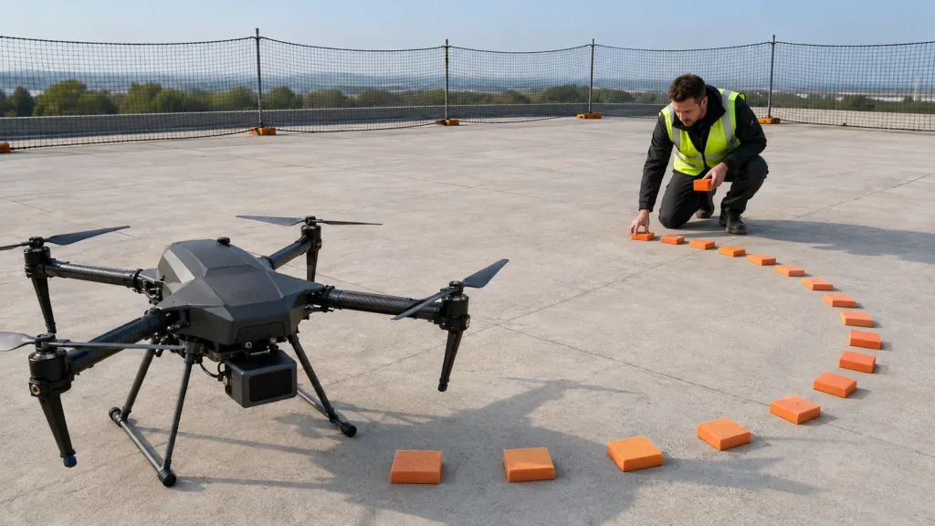
- Fly short guarded passes over a slope transition and a stepped retaining edge inside the expected hold band.
- Review the synchronized logs to see whether measured clearance stays believable as the terrain rises or falls.
- Repeat a climb above the intended LiDAR support band to confirm the team understands the fallback to barometric height control.
This workflow is practical because it tests the exact question the pilot and engineer care about: whether the aircraft can hold a stable clearance band over changing terrain without creating mystery behavior when the LiDAR signal stops being the primary low-altitude aid.
Common mistakes when validating drone altitude hold LiDAR
- Using the indoor range claim as the acceptance threshold for an outdoor low-altitude workflow.
- Testing only on flat concrete or inside a lab instead of on terrain steps and slopes.
- Assuming a good hover proves safe fallback above the sensor's usable range.
- Ignoring pitch-angle occlusion from landing gear, payloads, or the airframe belly.
- Logging only the controller result and not the raw or intermediate LiDAR evidence.
- Tuning the flight controller before the team can explain whether the distance data itself is trustworthy.
RFQ and engineering checklist
| Checklist item | Why it belongs in the validation sheet |
|---|---|
| Target hold band | Defines where the LiDAR is expected to help and where fallback begins. |
| Downward mount angle | Prevents a nominal FoV from hiding the wrong ground region during pitch. |
| Terrain transition test set | Forces slope and step changes into the first meaningful outdoor run. |
| Range-limit fallback check | Confirms what the aircraft does once it exceeds usable LiDAR support distance. |
| Preferred first interface | Reduces time to a replayable dataset. |
| Log synchronization plan | Makes controller events explainable after the flight. |
| Reject conditions | Prevents field teams from debating ambiguous behavior without a pass/fail rule. |
| Contact packet for vendor discussion | Helps the next support conversation start with real terrain, altitude band, and data-path constraints. |
When a compact dToF module is ready for the next flight test
If your team can already define the low-altitude band, the terrain transitions that matter, the fallback behavior, and the replay path for weak runs, a compact LiDAR module can move from bench review into a defensible flight-test workflow quickly. If those definitions are still vague, tighten the validation sheet before spending more tuning time.
Purpleriver's featured MRP-LD1 solid-state dToF sensor is relevant for teams evaluating altitude hold, terrain following, obstacle awareness, and compact UAV integration. To discuss fit with your own aircraft, use the contact page and include your target hold band, mount angle, controller stack, and logging workflow.